
Manually activated slider clip

a slider and clip technology, applied in the field of slider clips, can solve the problems of not being reliable, difficult, if not impossible, to produce a slider zipper for containment purposes, and being cumbersome at best, so as to reduce or eliminate the requirement of pre-activation of the zipper

Active Publication Date: 2010-01-21
ILLINOIS TOOL WORKS INC
View PDF24 Cites 10 Cited by
  • Summary
  • Abstract
  • Description
  • Claims
  • Application Information

AI Technical Summary

Benefits of technology

The present invention provides a clip or slider design that can be used with zipper designs where the profiles are separated by pressing them together. This design eliminates the need for pre-activation of the zipper and allows for easy opening and closing with minimal finger pressure. Additionally, it can be used for child-resistant packaging or vacuum packaging.

Problems solved by technology

With at least some small amount of pre-activation required for virtually all slider zipper, it is difficult, if not impossible, to reliable produce a slider zipper for containment purposes.
This is unwieldy at best, and has not proven to be reliable.

Method used


Image

  • Manually activated slider clip
  • Manually activated slider clip
  • Manually activated slider clip

Examples


Embodiment Construction

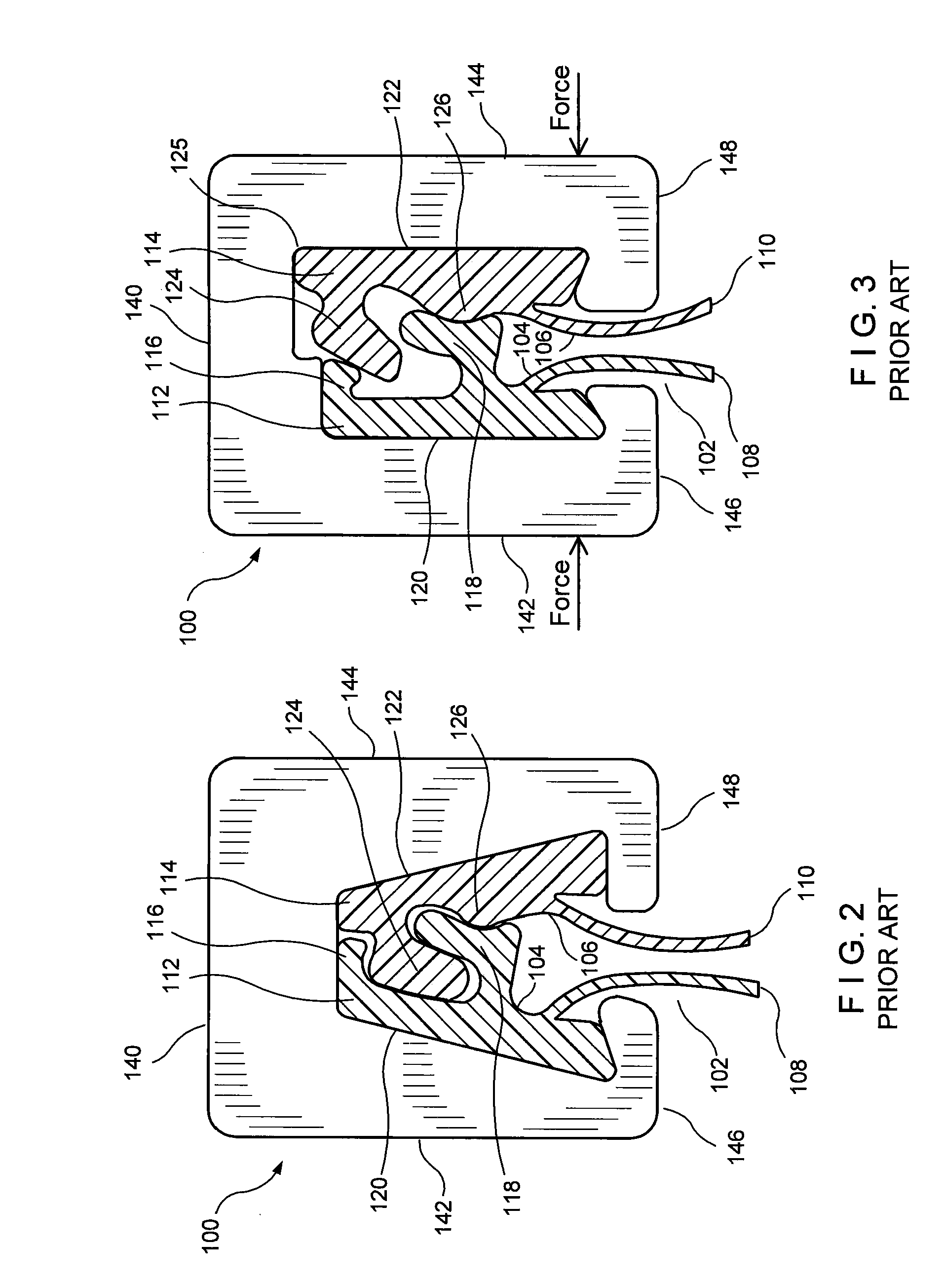
[0018]Referring now to the drawings in detail wherein like numerals indicate like elements throughout the several views, one sees that FIG. 1 is a diagram of a prior art slider 200 which is mounted on a zipper 202 which includes first profile 204 and second profile 206. First and second profiles 204, 206 include respective first and second flanges 208, 210 which extend from respective first and second interlocking elements 212, 214. First interlocking element 212 is configured as a female element while second interlocking element 214 is configured as a male element. Slider 200 includes a top wall 220 and first and second sidewalls 222, 224. Plough 226 extends from the undersurface of top wall 220 so as to extend between first and second interlocking elements 212, 214 and exert an outwardly extending force, as indicated by the arrows, to separate and force apart the first and second profiles 204, 206.

[0019]By contrast, the slider 100 illustrated in FIGS. 2 and 3 (which illustrate the...


PUM


Abstract

A slider is provided which can be mounted on a zipper without any pre-activation, particularly zippers which are opened by squeezing together a portion of the profiles wherein a fulcrum effect is achieved to separate the profiles. The slider omits at least part of the zipper opening elements so that the user must squeeze the slider together in order to urge the zipper profiles apart thereby opening the zipper.

Description

[0001]This application claims priority under 35 U.S.C. §119(e) of U.S. provisional application Ser. No. 61 / 080,826 filed on Jul. 15, 2008, the contents of which are hereby incorporated by reference.BACKGROUND OF THE INVENTION[0002]1. Field of the Invention[0003]The present invention pertains to a slider clip used with a slider zipper in a reclosable package or bag, whereby the user applies manual force to the clip in order to activate and open the zipper as the clip is slid from the closed position to the open position.[0004]2. Description of the Prior Art[0005]In the prior art of reclosable packages, it is known to use zippers with profiles with interlocking arms wherein the profiles are pressed together to open the zipper (i.e., to separate the profiles), such as is disclosed in U.S. Pat. No. 6,047,450 issued on Apr. 11, 2000 and U.S. Pat. No. 6,182,337 issued on Feb. 6, 2001, both entitled “Slider Zipper Assembly” and issued to Machacek and Kobetsky. Similar prior art includes U....

Claims


Application Information

Patent Timeline
Patent Type & Authority Applications(United States)
IPC IPC(8): A44B19/26
CPCY10T24/2534Y10T24/2532Y10T24/2582B65D33/2591B65D33/2588
Inventor ANZINI, DAVID J.
Owner ILLINOIS TOOL WORKS INC
Learn More