
Beam formed of plank and method for manufacturing the same

Inactive Publication Date: 2010-01-14
HWASHIN CO LTD
View PDF2 Cites 14 Cited by
  • Summary
  • Abstract
  • Description
  • Claims
  • Application Information

AI Technical Summary

Benefits of technology

[0013]The present invention is conceived to solve the problems of the conventional techniques as described above, and an aspect of the present invention is to provide a beam that is formed of a plank to facilitate formation of a shape capable of improving rigidity of the beam, and a method for manufacturing the same.

Problems solved by technology

Since a conventional torsion beam is made by processing a cylindrical pipe, the conventional method cannot produce a torsion beam that has various and continuous cross-sectional shapes along the torsion beam.
Further, although a wider cross-sectional area of a connection part between the torsion beam and the trailing arm imparts a higher rigidity to the torsion beam, the conventional torsion beam is difficult to have an increased cross-sectional area of the connection part due to the use of the pipe-shaped beam for manufacturing the torsion beam.

Method used


Image

  • Beam formed of plank and method for manufacturing the same
  • Beam formed of plank and method for manufacturing the same
  • Beam formed of plank and method for manufacturing the same

Examples


first embodiment

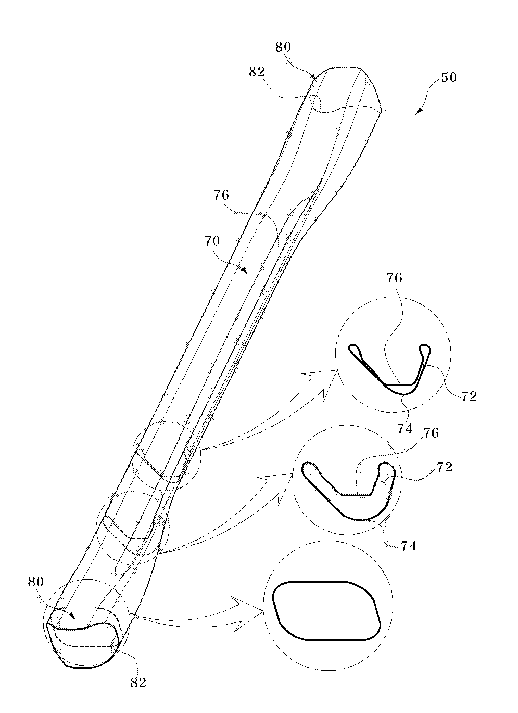
[0042]Referring to FIGS. 4 to 6, a beam according to the present invention is formed of a plank, and includes a body 70 formed by bending a work object of a plank 10 (see FIG. 8), connection parts 80 formed at opposite ends of the body 70 to engage with other members, and a bent part 74 formed along the body 70.

[0043]Herein, the beam formed of the plank is a torsion beam 50 for vehicles, and is coupled to a pair of trailing arms (not shown) via the connection parts 80 formed at the opposite ends of the beam.

[0044]The connection part 80 has a substantially rectangular pipe-shaped cross-section with a distance between upper and lower surfaces gradually decreasing toward the body 70, which is formed to have a “∩”-shaped or “Λ”-shaped cross-section via the bent part 74.

[0045]With this configuration, the torsion beam 50 for supporting the trailing arms 50 has improved torsion and transverse rigidity.

[0046]Further, the body 70 has a space 72 formed therein, so that spring rigidity of the ...

second embodiment

[0081] the connection part 180 is provided with an extension part 200 which increases a cross-sectional area of the connection part 180.

[0082]As the cross-sectional area of the connection part 180 is increased by the extension part 200, the trailing arm is coupled to the connection part 180 through an enlarged section of the connection part 180 which restricts the trailing arm coupled to the connection part 180, so that a transverse force transferred from an axle of a vehicle to the torsion beam through each of the trailing arms is applied to the enlarged section of the connection part 180, thereby improving durability of the connection part 180.

[0083]As a result, the rigidity of the torsion beam 150 capable of enduring the lateral force, that is, transverse rigidity of the torsion beam 150, is improved.

[0084]In addition, since the torsion beam 150 of this embodiment is also made of a plank-shaped work object 100, the formation of a seating groove 182 and a connection part 180 adapt...


PUM

PropertyMeasurementUnit
Shapeaaaaaaaaaa
Stiffnessaaaaaaaaaa

Abstract

A beam formed of a plank and a method for manufacturing the same are disclosed. The beam includes a body formed by bending a work object of a plank; a connection part formed at both ends of the body to engage with other members, and a bent part formed along the body. The beam facilitates formation of a shape imparting improved rigidity to the beam.

Description

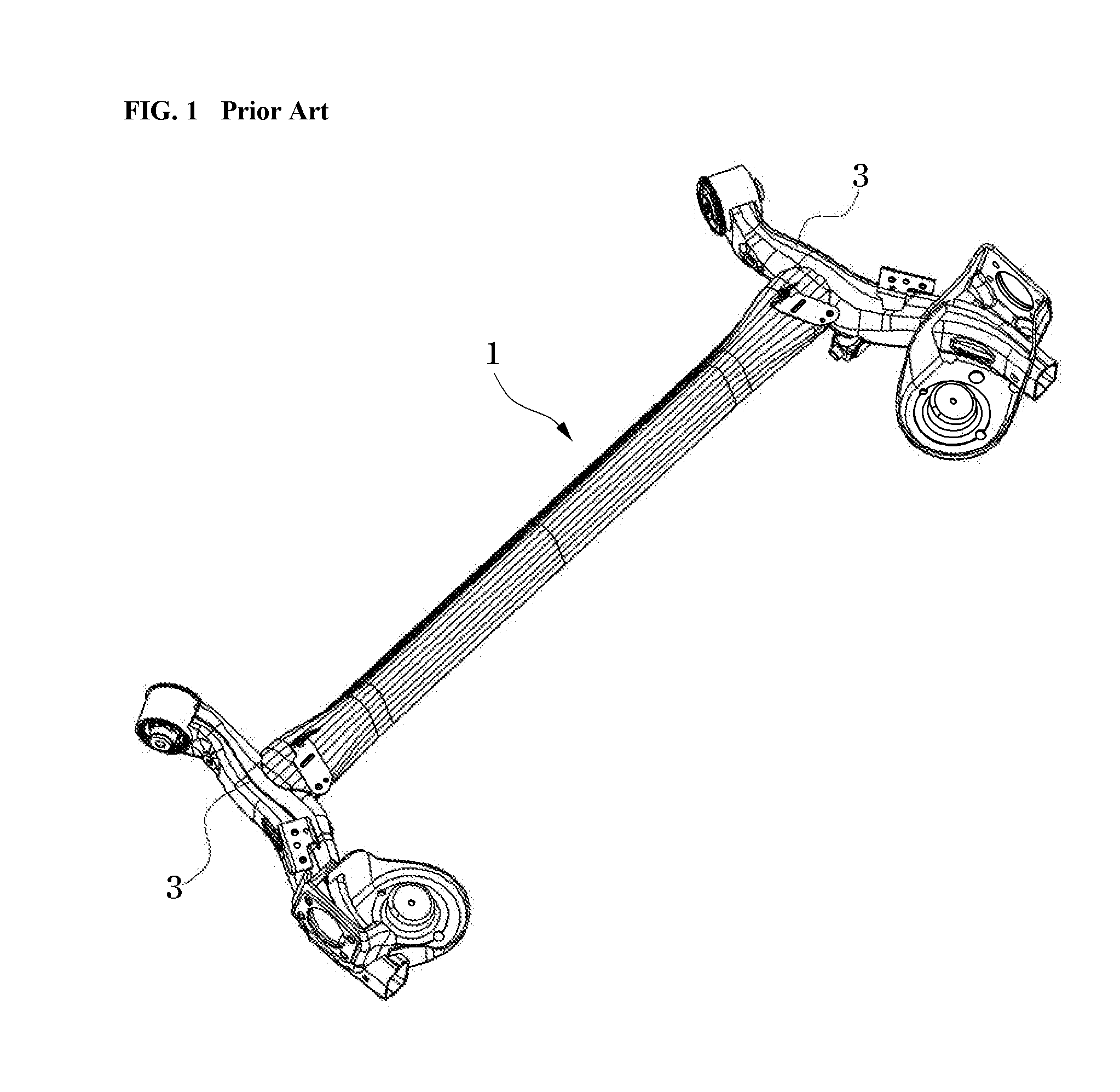
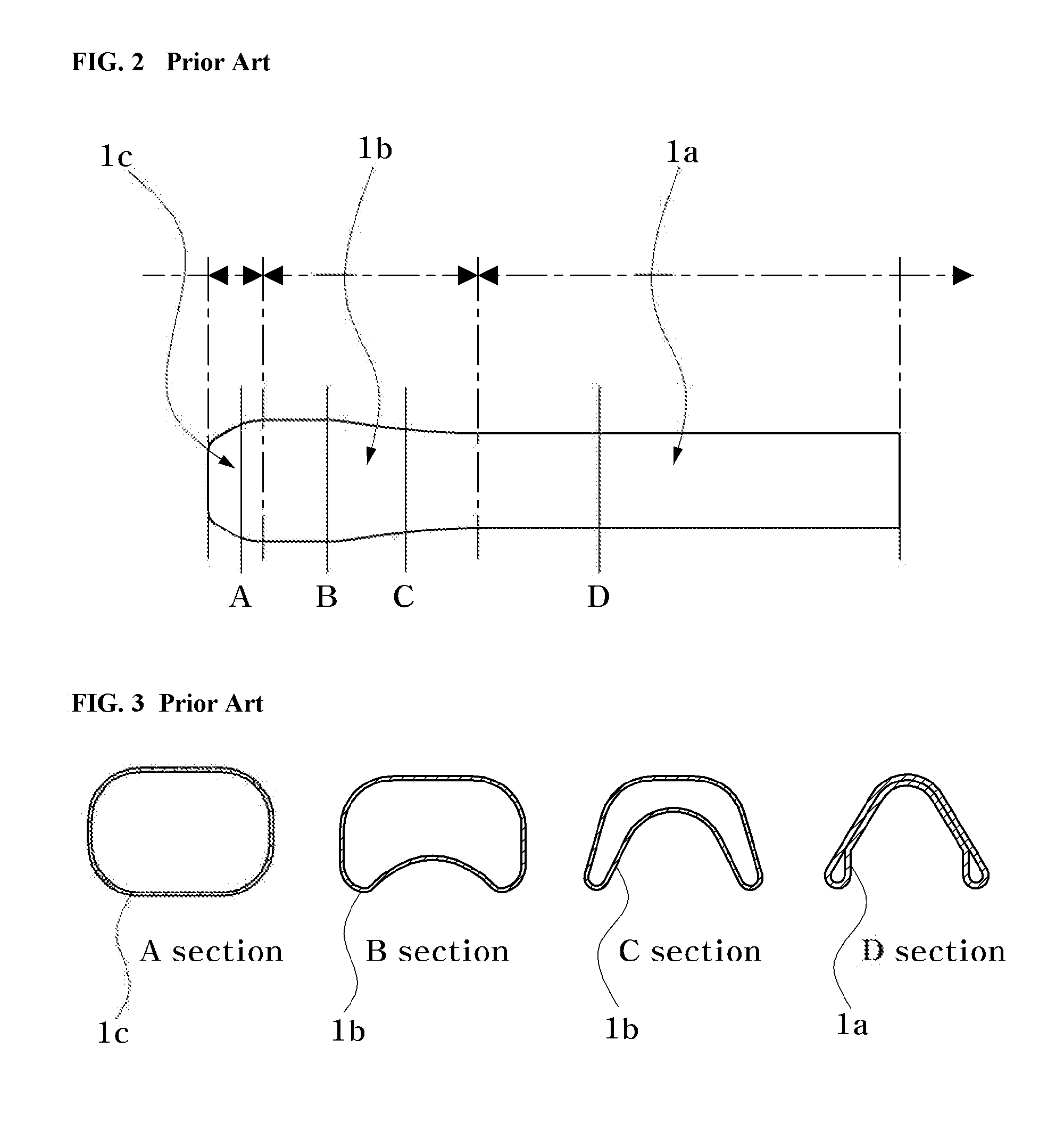
BACKGROUND OF THE INVENTION[0001]1. Field of the Invention[0002]The present invention relates to a beam formed of a plank, and more particularly, to a beam that is formed of a plank to facilitate formation of a shape capable of improving rigidity of the beam, and a method for manufacturing the same.[0003]2. Description of the Related Art[0004]FIG. 1 is a perspective view of a conventional torsion beam for a rear-wheel suspension system of a vehicle, FIG. 2 is a plan view of the conventional torsion beam, and FIG. 3 is cross-sectional views respectively taken along lines A, B, C, and D shown in FIG. 2.[0005]Referring to FIGS. 1 to 3, a torsion beam suspension of a rear-wheel suspension system for a vehicle generally includes a torsion beam 1, and a trailing arm 3 connected in a front-rear direction to either end of the torsion beam 1 to maintain a posture of the vehicle when the vehicle corners. The torsion beam 1 must have torsion rigidity and bending rigidity.[0006]Conventionally, ...

Claims


Application Information

Patent Timeline
IPC IPC(8): B32B3/06B21D53/88
CPCB21D35/00B21D53/88B60G21/051Y10T29/49622B60G2206/8102B60G2206/8201Y10T428/24008B60G2206/202B60G7/00B60G7/02
Inventor KIM, TAE JUN
Owner HWASHIN CO LTD
Learn More