
Tool suspension device

Inactive Publication Date: 2010-01-07
KAO JUI CHIEN
View PDF11 Cites 26 Cited by
  • Summary
  • Abstract
  • Description
  • Claims
  • Application Information

AI Technical Summary

Benefits of technology

[0007]The main objective of the present invention is to provide a tool suspension device that can be movably adjusted to hold tools conveniently and easily.

Problems solved by technology

However, the stationary holders are immovably connected to the baseboard and an interval between adjacent stationary holders is fixed, the interval between adjacent stationary holders cannot be adjusted to match different widths of different tools, and this is inconvenient in use.

Method used


Image

  • Tool suspension device
  • Tool suspension device
  • Tool suspension device

Examples


Embodiment Construction

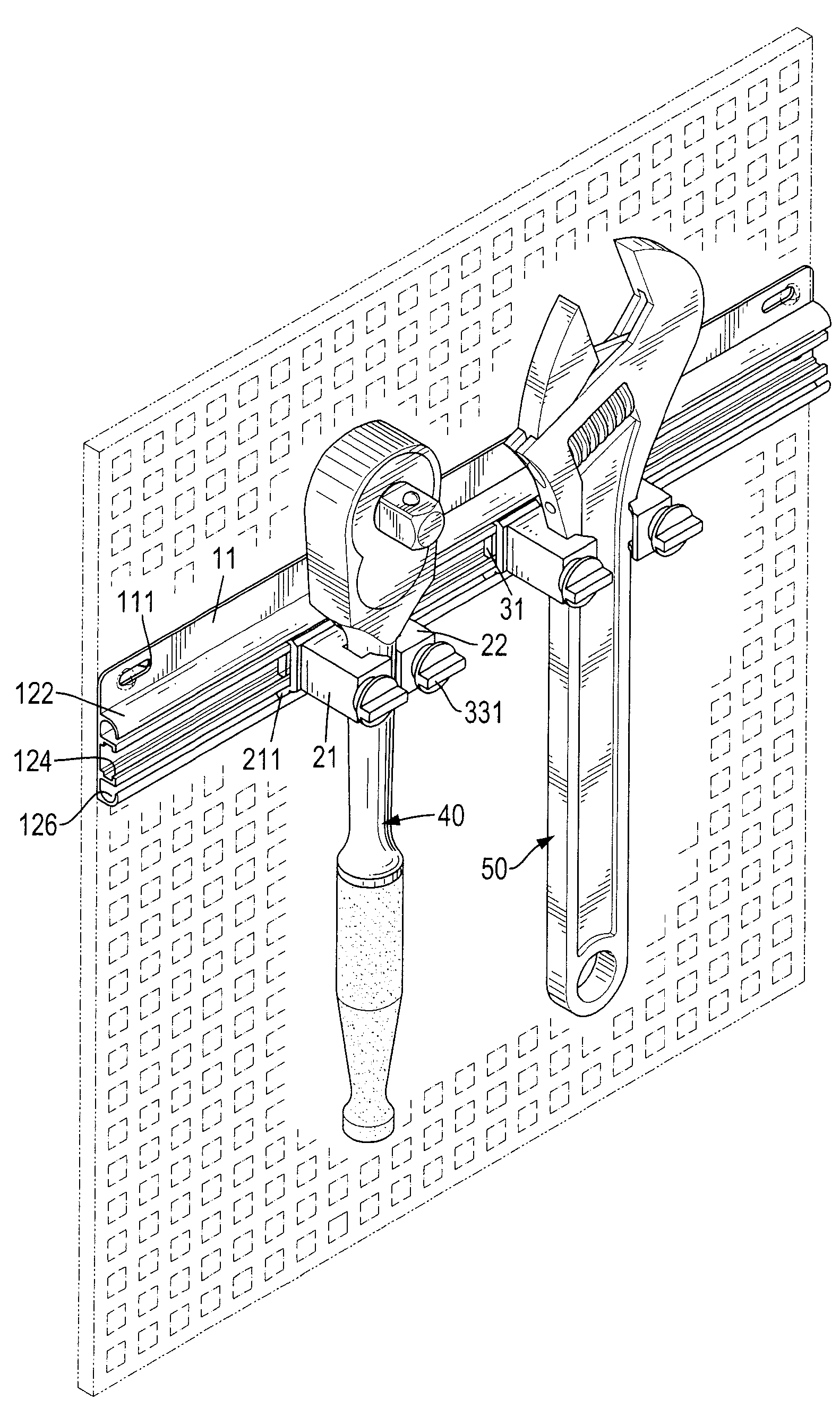
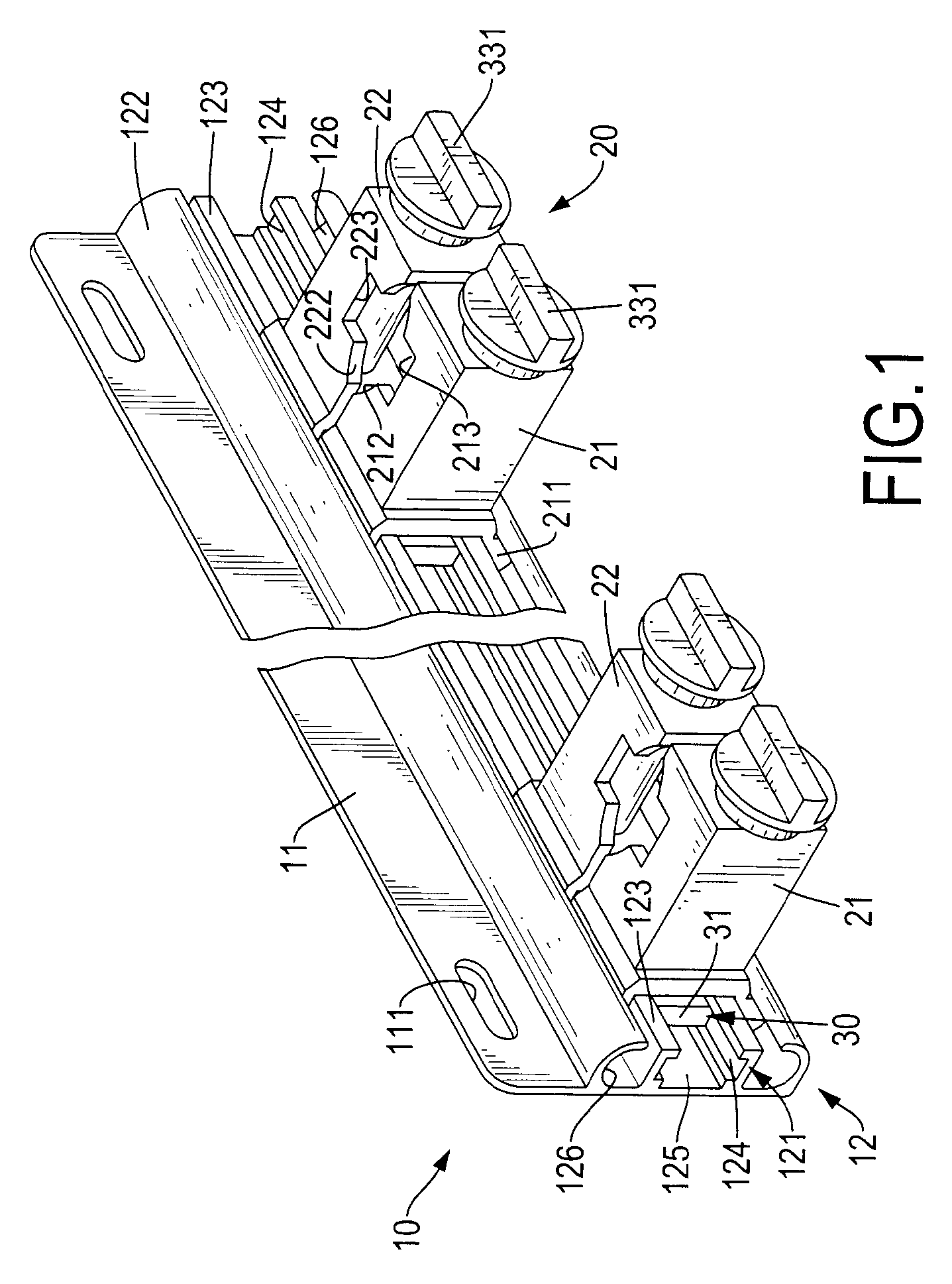
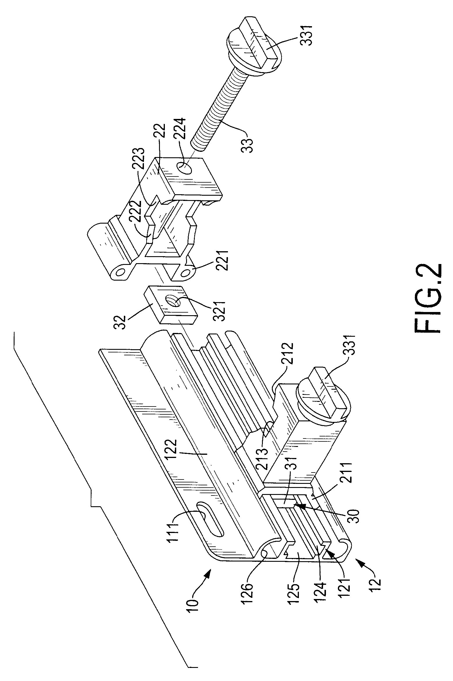
[0017]With reference to FIGS. 1, 2 and 4, a tool suspension device in accordance with the present invention has a base bracket (10), multiple clamping elements (20) and multiple sliding elements (30).

[0018]The base bracket (10) may be hang on a mounting surface such as a wall, a perfboard or other such vertical surface and has a baseboard (11) and a rail bracket (12).

[0019]The baseboard (11) has a front surface and multiple optional hanging holes (111). The hanging holes (111) are formed through the baseboard (11) to make the baseboard (11) mounting on the wall or the perfboard.

[0020]The rail bracket (12) is formed on the front surface of the baseboard (11) and has an inner rail (121) and an outer rail (122).

[0021]The inner rail (121) is formed on the front surface of the baseboard (11) and has two rail panels (123) and an optional chamber (125). The rail panels (123) are transversely formed on the front surface of the baseboard (11) and are parallel with each other, and each rail p...


PUM


Abstract

A tool suspension device has a base bracket, multiple clamping elements and multiple sliding elements. The base bracket has a baseboard and a rail bracket. The rail bracket is formed on the baseboard and has an inner rail and an outer rail. The clamping elements are mounted slidably on the rail bracket and each has two clamps in pairs. Each clamp is mounted slidably on the outer rail and has two hooks and an arm. The hooks are mounted slidably in the outer rail. The arm is formed with the hooks and has a mounting hole. The sliding elements are mounted slidably in the rail bracket, are connected to the clamping elements and each has two sliding plates and two adjusting bolts. The sliding plates are mounted in the inner rail. The adjusting bolts are mounted in the mounting holes and connected to the sliding plates.

Description

BACKGROUND OF THE INVENTION[0001]1. Field of the Invention[0002]The present invention relates to a tool suspension device, especially to a tool suspension device that can be movably adjusted to hold tools conveniently and easily.[0003]2. Description of the Prior Arts[0004]A conventional suspension device is used to hold tools such as wrenches, screwdrivers or sockets on a wall and has a baseboard and multiple stationary holders. The baseboard has multiple hanging holes formed through the baseboard to allow the baseboard to be mounted on the wall by fasteners. The stationary holders are fixed loops connected securely to the baseboard to hold tools on the conventional suspension device.[0005]However, the stationary holders are immovably connected to the baseboard and an interval between adjacent stationary holders is fixed, the interval between adjacent stationary holders cannot be adjusted to match different widths of different tools, and this is inconvenient in use.[0006]To overcome...

Claims


Application Information

Patent Timeline
IPC IPC(8): A47F5/08
CPCB25H3/04
Inventor KAO, JUI-CHIEN
Owner KAO JUI CHIEN
Learn More