Railroad switch machine

a switch machine and switch technology, applied in the direction of railway signalling, point operation from vehicles, transportation and packaging, etc., can solve the problems of train derailing, train engineer may not be able to stop his train soon, and trains are typically unable to stop very quickly

Active Publication Date: 2009-12-17
ANSALDO STS USA INC
View PDF6 Cites 11 Cited by
  • Summary
  • Abstract
  • Description
  • Claims
  • Application Information

AI Technical Summary

Benefits of technology

[0007]In one embodiment, a switch machine for moving a set of railroad points is provided. The switch machine includes a motor that is operatively coupled to the points for selectively moving the points. The motor is also operatively coupled to a power supply through a normal connection path and a reverse connection path. The motor is structured to be selectively driven in a normal direction for moving the points toward a normal position when power is applied thereto by the power supply through the normal connection path and in a reverse direction when power is applied thereto by the power supply through the reverse connection path. The switch machine further includes a first relay having one or more first normally open contacts and one or more first normally closed contacts provided in the normal connection path and a second relay having one or more second normally open contacts and one or more second normally closed contacts provided in the reverse connection path. Each of the one or more first normally open contacts is associated with a corresponding one of the one or more first normally closed contacts, and similarly, each of the one or more second normally open contacts is associated with a corresponding one of the one or more second normally closed contacts. The first relay is structured such that each first normally closed contact and the corresponding first normally open contact cannot be simultaneously closed and the second relay is structured such that each second normally closed contact and the corresponding second normally open contact cannot be simultaneously closed.

Problems solved by technology

Of all of the possible scenarios for a malfunction of a switch machine, the one that railroad operators most wish to avoid is a control malfunction causing the switch machine to suddenly change the position of a portion of track at a switch point just at the moment where a train is approaching the switch point such that it is too late for the train to stop before reaching the switch point with the result that the train is derailed.
Contact erosion is the result of there being a large amount of electrical current being switched by the relay, which is the case in a switch machine since the motor required to move a portion of track between two switch positions is typically a large motor requiring a great deal of power.
With current state of the art there is no mitigation of arcing and resultant contact erosion and thus the switching devices must be replaced periodically.
Although indicator lights at the switch point will warn the train engineer operating the train that the switch point has suddenly started moving the portion of track again, trains are typically unable to stop very quickly, and the train engineer may not be able to stop his train soon enough to avoid derailment or collision.
Another issue affecting reliability of switching machines is an occasion in which the movement of a portion of track from one switch position to another cannot be completed because of either a mechanical malfunction or an obstruction preventing the portion of track from moving to the new switch position.
In such situations, there is the risk of damaging the motor of the switch machine if the motor is allowed to continue struggling to move the portion of track.
Such a use of a relay is effective, but adds considerably to the cost of the switching machine.

Method used


Image

  • Railroad switch machine
  • Railroad switch machine
  • Railroad switch machine

Examples


Embodiment Construction

[0016]Directional phrases used herein, such as, for example and without limitation, top, bottom, left, right, upper, lower, front, back, and derivatives thereof, relate to the orientation of the elements shown in the drawings and are not limiting upon the claims unless expressly recited therein.

[0017]As employed herein, the statement that two or more parts or components are “coupled” together shall mean that the parts are joined or operate together either directly or through one or more intermediate parts or components.

[0018]As employed herein, the statement that two or more parts or components “engage” one another shall mean that the parts exert a force against one another either directly or through one or more intermediate parts or components.

[0019]As employed herein, the term “number” shall mean one or an integer greater than one (i.e., a plurality).

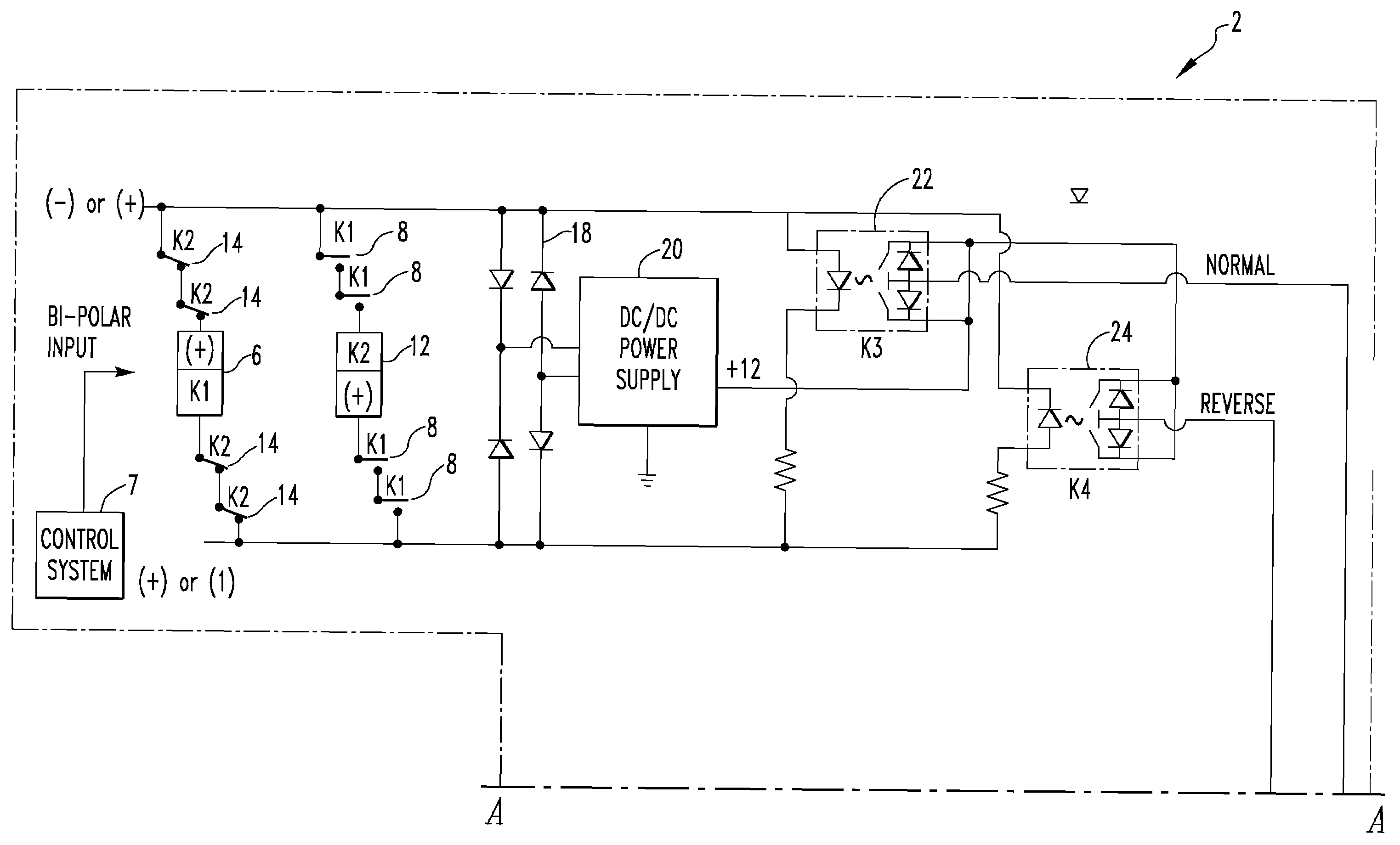
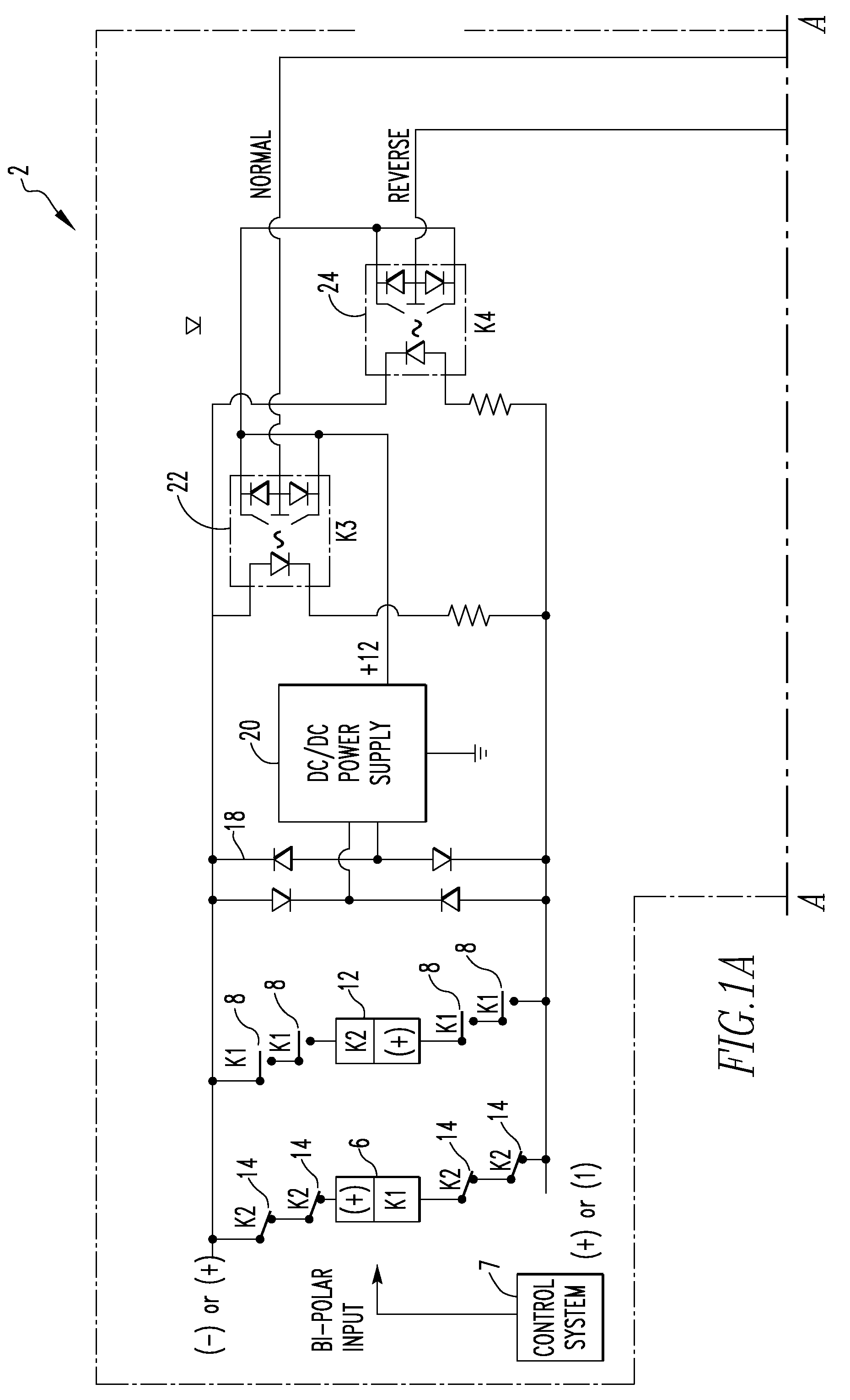
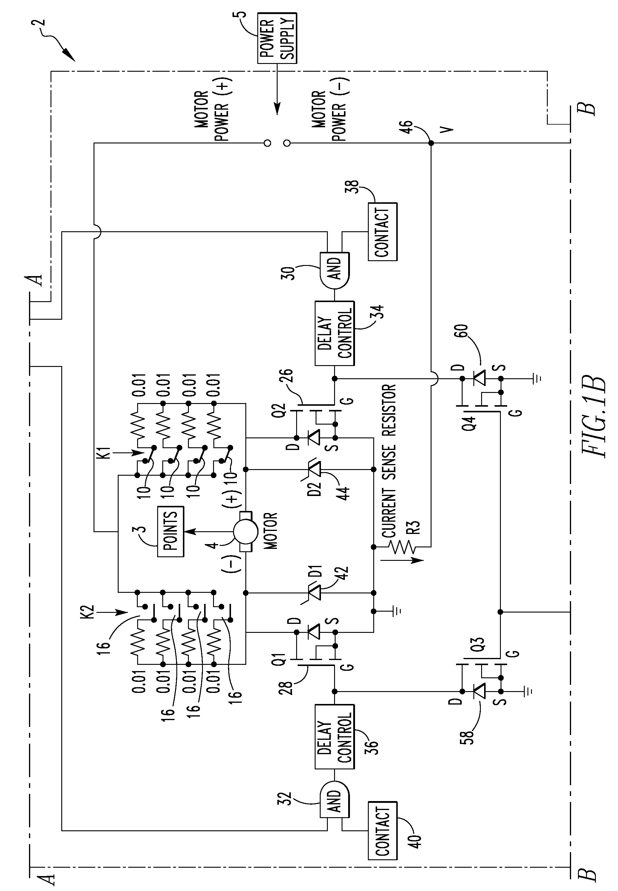
[0020]FIGS. 1A, 1B and 1C are a schematic diagram of a switch machine 2 according to one embodiment of the present invention. As is ...


PUM


Abstract

A switch machine that includes a first relay having first normally open contacts and first normally closed contacts provided in the normal motor connection path and a second relay having second normally open contacts and second normally closed contacts provided in the reverse motor connection path. The normally open and closed contacts of each relay are associated in pairs and the first relays are structured such that each normally closed contact and the corresponding normally open contact cannot be simultaneously closed. Also, a method of protecting a motor of a switch machine that includes integrating a current being drawn by the motor and opening a motor circuit that includes the motor if the integrated current exceeds a threshold.

Description

CROSS-REFERENCE TO RELATED APPLICATIONS[0001]This application claims the benefit of U.S. Provisional Application No. 61 / 061,001, entitled “Biased Neutral Controller for M23E Switch Machine”, filed on Jun. 12, 2008, the disclosure of which are incorporated herein by reference.FIELD OF THE INVENTION[0002]The present invention relates to railroad switch machines, and in particular to a railroad switch machine employing a set of interlocking relays and / or methods for protecting the switch machine against contact welding and thermal damage.BACKGROUND OF THE INVENTION[0003]Switch machines are used to move a portion of track at a switch point in a railway system to switch a train from one track to another. It is commonplace for personnel controlling switch machines to be located hundreds or even thousands of miles away from the locations of switch points 3 at which the switch machines are installed such that they cannot observe the operation of the switch machine with their own eyes. Such ...

Claims


Application Information

Patent Timeline
Patent Type & Authority Applications(United States)
IPC IPC(8): B61L5/06
CPCB61L5/062B61L1/20
Inventor FRANKE, RAYMOND C.
Owner ANSALDO STS USA INC
Why Eureka
Try Eureka