Aquatic light emitting device

a technology of light-emitting devices and water-based batteries, which is applied in waterborne vessels, climate sustainability, and power-in-place devices, etc., can solve the problems of frequent out-of-orderness of light-emitting devices and increase the cost of maintenance and repair, and achieve the effect of giving buoyancy

Inactive Publication Date: 2009-12-10
KUMHO ELECTRIC INC
View PDF4 Cites 11 Cited by
  • Summary
  • Abstract
  • Description
  • Claims
  • Application Information

AI Technical Summary

Benefits of technology

[0010]In order to accomplish the object above, an aquatic light emitting device according to the present invention comprises a point light emitting unit and a linear light emitting unit. The point light emitting unit comprises a floating member part, a light source part and a power supply part. The floating member part includes a hollow body which has an internal space isolated from the outside so as to give buoyancy, one or more junction portions formed on an outer surface thereof, a light inlet opening formed on an upper part, and a string connected to a lower surface of the hollow body. The light source part is attached to the upper surface of the

Problems solved by technology

Since a nautical mark, in particular, a light on-off device mounted to a floating member is operated unattended and is not easily managed because of geographical factors, there is a need to supply a stable power source and maintenance and repair are continuously required.
However, the white light bulb is a light source in which heat is converted into light by means of the filament and has the problems of overheating caused by long term use, vibrations caused by waves, shocks caused by collisions between a ship and the light on-off devices and so on.
In addition, the bulb exchanger used in the bulb type light on-off device has a structure in which the small-sized motor is coupled with a reduction gear unit, and so the bulb exchanger is frequently out of order due to a breakdown in the gear unit.
However, since the light on-off device utilizing LEDs is integrally assembled in one body for protection from water, vibration and so on, it is difficult to repair the light on-off device using an LED on the sea and the whole light on-off device has to be replaced if it breaks down, and so the cost for maintenance and repair is increased.

Method used


Image

  • Aquatic light emitting device
  • Aquatic light emitting device
  • Aquatic light emitting device

Examples


Embodiment Construction

[0016]Hereinafter, the preferred embodiment of the present invention is described in detail with reference with the accompanying drawings.

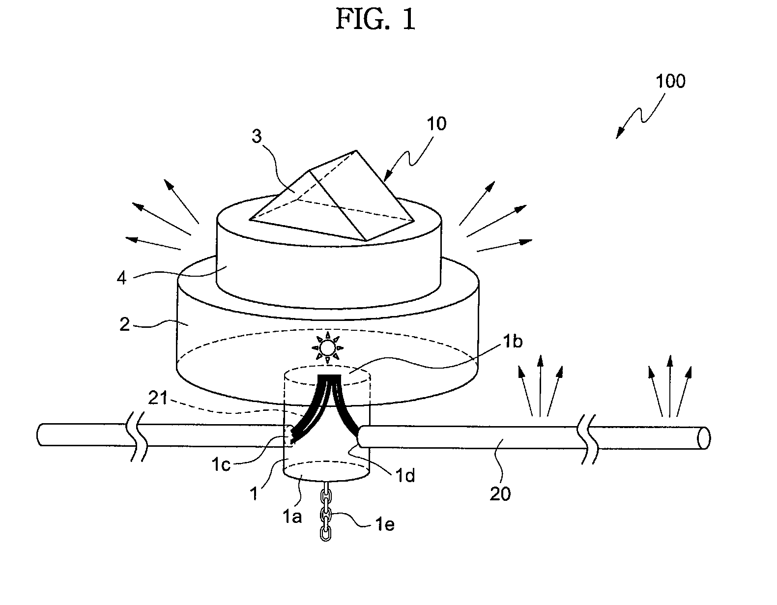
[0017]FIG. 1 is a perspective view of an aquatic light emitting device according to the present invention.

[0018]The aquatic light emitting device 100 according to the present invention comprises a point light emitting unit 10 and a linear light emitting part 20. The point light emitting unit 10 comprises a floating member part 1, a light source part 2 and a power supply part 3, and the linear light emitting part 20 includes an optical fiber surrounded by a transparent tube. The aquatic light emitting device illustrated in FIG. 1 is an example according to one embodiment of the present invention.

[0019]The floating member part 1 is a cylindrical or polygonal hollow body. The lower part of the hollow body may be equal to or larger than the upper part in outer circumference. The hollow body has an upper surface 1b, a lower surface 1a and junction part...


PUM


Abstract

An aquatic light emitting device comprising a plurality of point light emitting units and a plurality of linear light emitting units is disclosed. The point light emitting unit comprises a floating member part, a light source part, and a power supply part. The floating member includes a hollow body which has an internal space isolated from the outside so as to give buoyancy, one or more junction portions formed on an outer surface thereof, and has a light inlet opening formed on an upper part, and a string connected to a lower surface of the hollow body. The light source part is attached to the upper surface of the floating member, has an isolated internal space with light outlet openings provided at the upper and lower surfaces thereof, and a light source and a light source control circuit contained in the isolated internal space. The power supply part is located on the upper surface of the light source part and includes a solar cell. The linear light emitting unit comprises at least one optical fiber which is introduced into the hollow body through a hole formed at the junction portion, one end of which is arranged at the light inlet opening of the hollow body, and part of which extends outwards through the junction portion, and is surrounded by a transparent tube.

Description

CROSS-REFERENCE TO RELATED APPLICATIONS[0001]This application claims priority from Korean Patent Application No. 10-2008-0053052 filed on Jun. 5, 2008, the contents of which are incorporated herein by reference in its entirety.BACKGROUND OF THE INVENTION[0002]The present invention relates to an aquatic light emitting device in which power is supplied semi-permanently through a solar cell, and one end of an optical fiber is disposed at a lower portion of a power source and light is transmitted to the other end of the optical fiber, whereby the light is diffused and scattered through the optical fiber to indicate a specific region in the line shape.[0003]Recently, marine transportation means have been developed that are frequently sailed on the sea or on rivers. Accordingly, risks such as natural hazards in the sea, sunken ships, and the like have increased and the protection of fisheries, fish farming and the like have increased. As a result, an artificial construction (nautical mark...

Claims


Application Information

Patent Timeline
IPC IPC(8): F21V31/00F21L4/00
CPCB63B22/166B63C7/26B63J2003/003F21S2/005Y02T70/70F21S9/037F21W2111/047G02B6/001F21S4/001F21S4/10Y02T70/00F21Y2115/10F21V2200/10
Inventor CHOI, GI-SEUNGLEE, JONG-CHANHER, IN-SUNGWEON, HYO-JINKIM, MIN-SU
Owner KUMHO ELECTRIC INC
Why Eureka
Try Eureka