
Multi-functional patient transfer device

a patient transfer and multi-functional technology, applied in the field of patient handling systems, can solve the problems of discomfort and injury to both patient and caregiver, increasing attention to patient handling, and existing approaches to patient handling having several limitations

Inactive Publication Date: 2009-10-08
HUNTLEIGH TECH LTD
View PDF99 Cites 50 Cited by
  • Summary
  • Abstract
  • Description
  • Claims
  • Application Information

AI Technical Summary

Benefits of technology

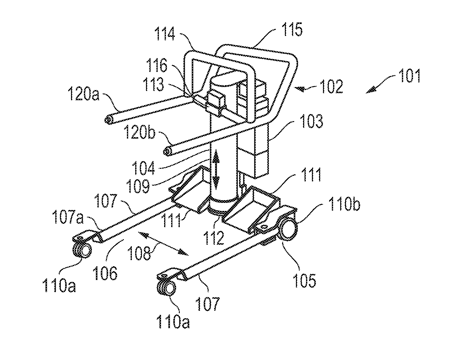
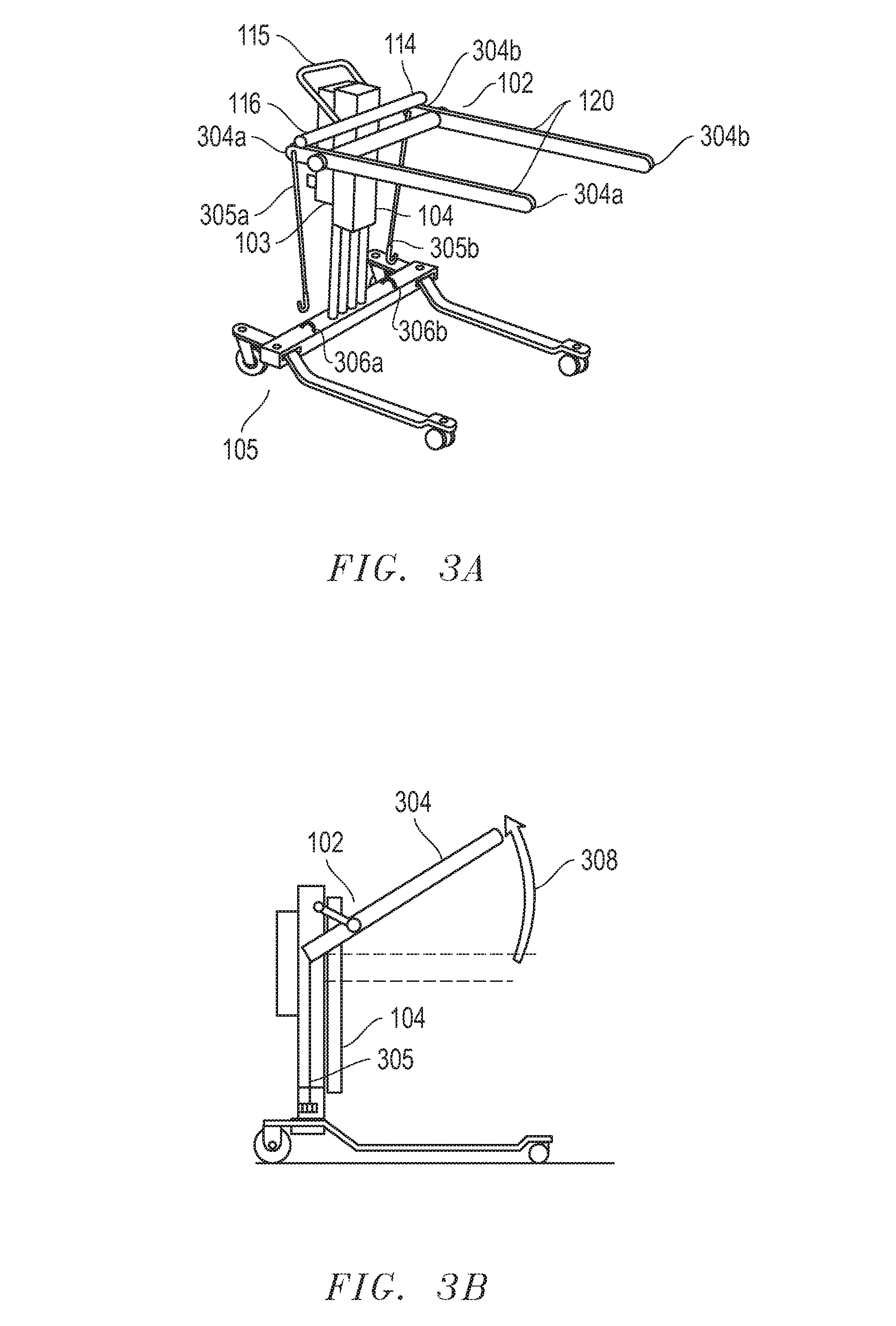
[0007]In another embodiment, the multi-functional patient transfer device may include a lift cart containing a central structure, frontal bars connectable to the central structure and having two arms that are approximately parallel, and a cable connectable to the frontal bars and to the lift cart. In this embodiment, the central structure is capable of raising and lowering the frontal bars. In addition, in this embodiment, the frontal bars may rotate between angles in which the arms extend outward from the lift cart with an approximately horizontal orientation and in which the arms extend upwards from the lift cart with an approximately vertical orientation. Also, in this embodiment, the cable may assist the rotation of the frontal bars when the central structure raises the frontal bars.

Problems solved by technology

The field of patient handling is gaining increased attention as a result of nursing shortages, caregiver injuries, and the rising incidence of obesity in western societies.
At the same time, existing approaches to patient handling have several limitations.
Such systems can lead to discomfort and injury to both patient and caregiver and, in many cases, require the presence of more than one caregiver.
Traditional mechanical solutions, such as floor-based hoists, ceiling lifts, and lateral transfer systems, have been shown to decrease the incidence of caregiver musculoskeletal injury but still present significant safety risks to patients.
In addition, traditional mechanical solutions are generally large, heavy, and difficult to transport.

Method used


Image

  • Multi-functional patient transfer device
  • Multi-functional patient transfer device
  • Multi-functional patient transfer device

Examples


Embodiment Construction

[0043]One preferred embodiment of the present invention comprises a multi-functional patient transfer device for transferring mobility-impaired patients. In one embodiment, the multi-functional patient transfer device includes a lift cart and one or more lift components. The lift components may attach to the lift cart and / or other lift components. As described in more detail below, the lift components may include frontal bars, a tabletop, a central arm, lifting forks, a hoist, a knee blocker, footrests, a transfer chair, detachable handles, and / or safety cushions. Embodiments of the present invention may also include one or more patient interfaces. The patient interfaces may attach to the lift cart and / or lifting components. As described in more detail below, the patient interfaces may include slings, chairs, straps, harnesses and / or transfer sheets. Example embodiments of methods of the present invention may include frontal transfers, lateral seated transfers, lateral bed transfers...


PUM


Abstract

One embodiment of the present invention comprises a multi-functional patient transfer device for transferring mobility-impaired patients. In one embodiment, the multi-functional patient transfer device includes a lift cart and one or more lift components. The lift components may attach to the lift cart and / or other lift components. The lift components may include frontal bars, a tabletop, a central arm, lifting forks, a hoist, a knee blocker, footrests, a transfer chair, detachable handles, and / or safety cushions. Embodiments of the present invention may include one or more patient interfaces. The patient interfaces may attach to the lift cart and / or one or more lifting components. The patient interfaces may include slings, chairs, straps, harnesses, and / or transfer sheets. In one embodiment, the patient interfaces may include foldable panels. In one embodiment, the patient interfaces may include a buttock / link support. Example embodiments of methods of the present invention may include frontal transfers, lateral seated transfers, lateral bed transfers, and sit-to-stand transitions.

Description

CROSS-REFERENCE TO RELATED APPLICATIONS[0001]This non-provisional application claims priority based upon prior U.S. Provisional Patent Application Ser. No. 61 / 042,587 filed Apr. 4, 2008 in the name of Frederic Palay and William E. Burak, Jr., entitled “Multi-Functional Patient Transfer Device,” the entirety of which is incorporated herein by reference.BACKGROUND OF THE INVENTION[0002]The present invention relates generally to patient handling systems and, more particularly, to patient handling systems with a multi-functional patient transfer device.[0003]The field of patient handling is gaining increased attention as a result of nursing shortages, caregiver injuries, and the rising incidence of obesity in western societies. At the same time, existing approaches to patient handling have several limitations. Manual patient handling systems, for example, generally rely on various lifting and sliding techniques to move a patient. Such systems can lead to discomfort and injury to both pa...

Claims


Application Information

Patent Timeline
IPC IPC(8): A61G7/10
CPCA61G5/14A61G7/1017A61G7/1019A61G7/1036A61G7/1051A61G2200/52A61G7/1059A61G7/1069A61G7/1096A61G2200/34A61G2200/36A61G7/1055
Inventor PALAY, FREDERICBURAK, JR., WILLIAM E.
Owner HUNTLEIGH TECH LTD
Learn More