
Method and apparatus for providing immersive surveillance

a technology of immersive surveillance and surveillance equipment, applied in the field of surveillance systems, can solve the problems of user not knowing how the activity relates to other locations, time-consuming and error-prone process of referring to a map or 3d model either on paper or on a computer, and the process of remembering a map or 3d model is also error-pron

Inactive Publication Date: 2009-09-24
L 3 COMM CORP
View PDF39 Cites 37 Cited by
  • Summary
  • Abstract
  • Description
  • Claims
  • Application Information

AI Technical Summary

Benefits of technology

"The present invention is a way to watch a scene using different cameras and a 3D model to give a realistic view. The user can choose different views and even walk through the scene to see moving objects. This technology makes it easier to monitor and surveillance situations."

Problems solved by technology

However, there are some fundamental problems with this approach.
First, if an event deserving attention occurs in one particular video, then the user does not know how the activity relates to other locations in the scene without referring to or remembering a map or 3D model of the scene.
The process of referring to a map or 3D model either on paper or on a computer is typically time-consuming and error-prone since a human is involved in the association of the camera view to the map or model.
The process of remembering a map or 3D model is also error-prone, and typically impossible when large numbers of cameras are used or if the site is large.
These two methods of predicting the new location of activity are error-prone, since typically the views from cameras are shown with respect to many different arbitrary coordinate systems that vary widely from camera to camera depending on how each camera was mounted during installation.
As more cameras are added to the system, the more difficult it is for the user to remember their orientations or to recognize the landmarks in the scene.
In addition, some parts of the scenes may contain no distinguishing landmarks at all.
This makes it difficult to observe the details of any event deserving attention in the video.
However, the problem with this approach is that the user will miss any activity that may be occurring in other videos while they are focusing on the single high-resolution video.

Method used


Image

  • Method and apparatus for providing immersive surveillance
  • Method and apparatus for providing immersive surveillance
  • Method and apparatus for providing immersive surveillance

Examples


Embodiment Construction

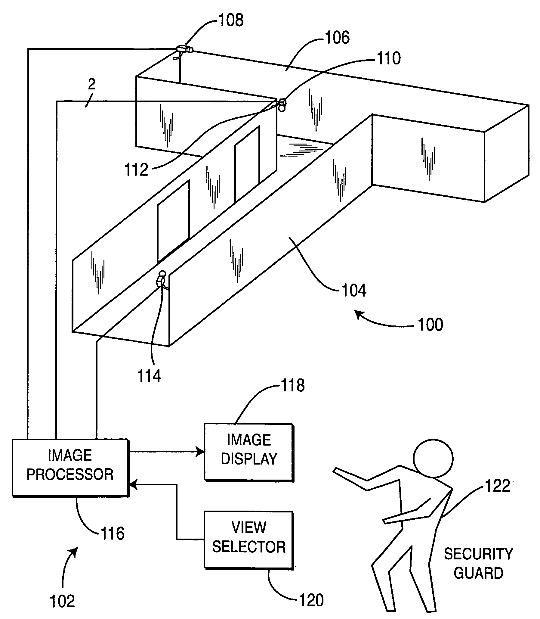
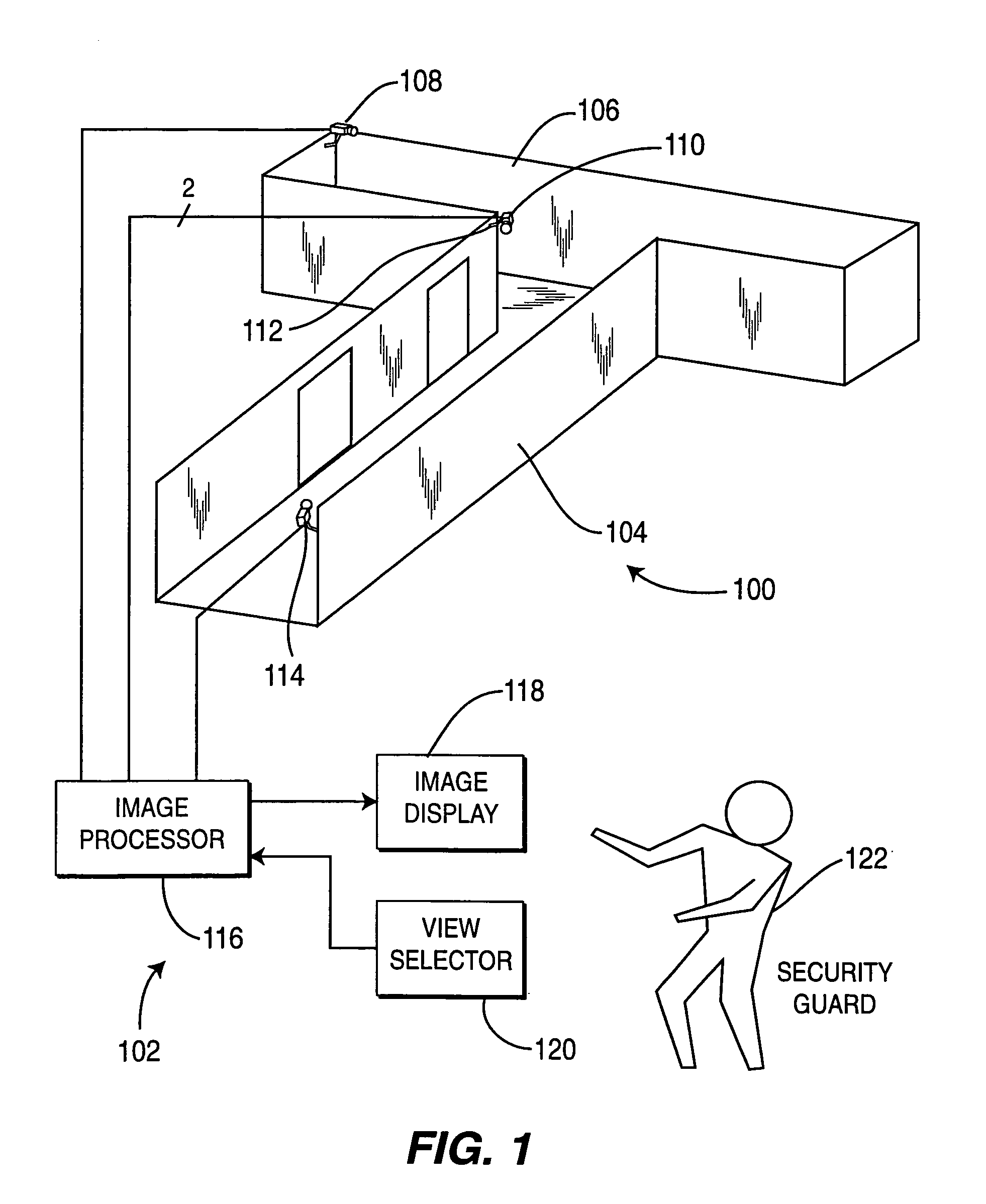
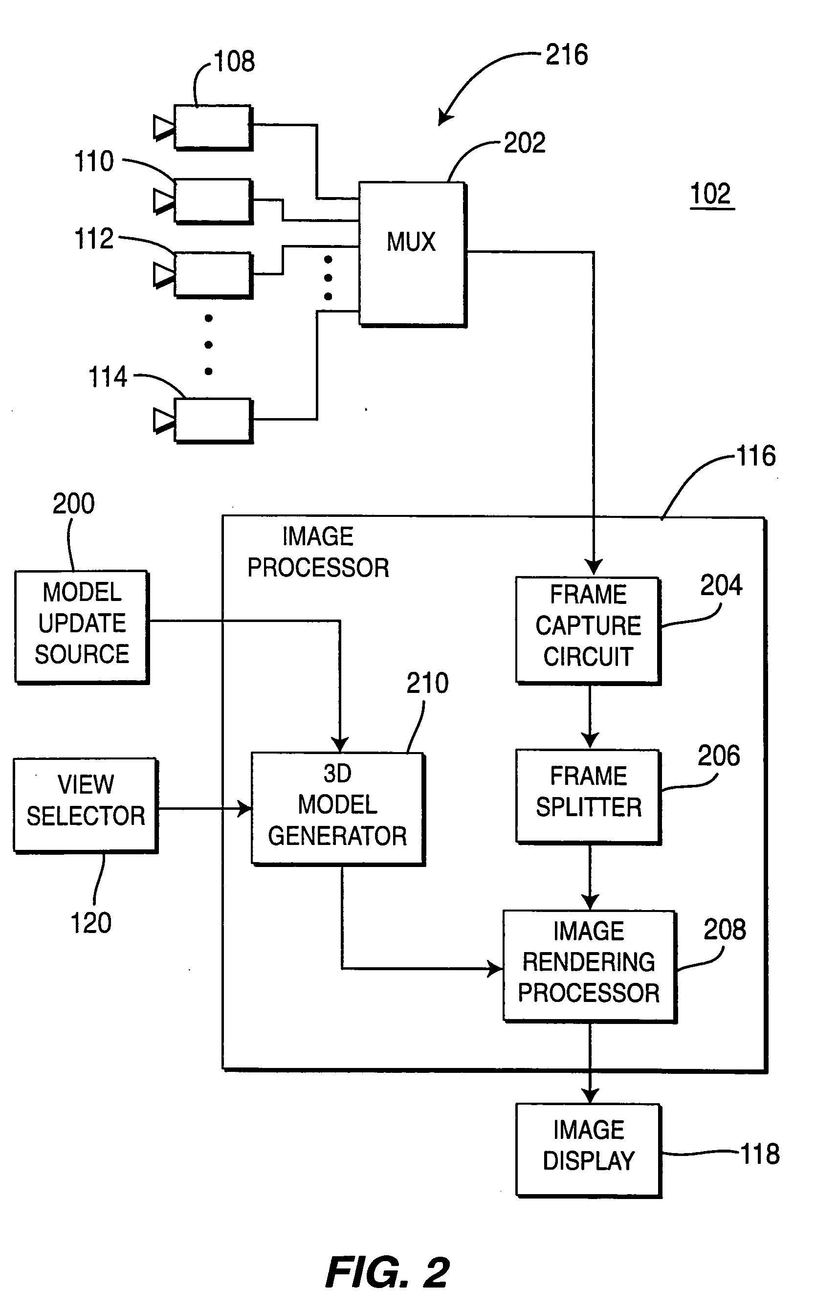
[0026]FIG. 1 depicts a block diagram of a surveillance system 102 as applied to monitor activity in a simple hallway scene 100. The hallway scene 100 comprises a first hallway 104 and a second hallway 106 that intersect and form a “T” shape. The hallway structure 100 is monitored by four cameras 108, 110, 112 and 114. These cameras are coupled to an image processor 116. The image processor processes the imagery from the cameras 108, 110, 112 and 114 to produce an image for display on an image display 118 (e.g., a video monitor). The particular view rendered from the various cameras is selectable using view selector 120. Generally, a user, e.g., a security guard 122, may be located either at the facility containing the scene 100 or may be remotely located from the scene 100. As shall be described below, the scene is modeled as a three-dimensional computer model and the imagery from the cameras 108, 110, 112, 114 is overlaid upon the model to provide a three-dimensional contextual vie...


PUM


Abstract

A method and apparatus for providing immersive surveillance wherein a remote security guard may monitor a scene using a variety of imagery sources that are rendered upon a model to provide a three-dimensional conceptual view of the scene. Using a view selector, the security guard may dynamically select a camera view to be displayed on his conceptual model, perform a walk through of the scene, identify moving objects and select the best view of those moving objects and so on.

Description

CROSS-REFERENCE TO RELATED APPLICATIONS[0001]This application claims benefit of U.S. provisional patent application Ser. No. 60 / 339,726, filed Nov. 2, 2001 which is herein incorporated by reference.GOVERNMENT RIGHTS IN THIS INVENTION[0002]This invention was made with U.S. government support under contract number F30602-00-C-0143. The U.S. government has certain rights in this invention.BACKGROUND OF THE INVENTION[0003]1. Field of the Invention[0004]The present invention generally relates to surveillance systems and, more particularly, relates to a method and apparatus for providing immersive surveillance.[0005]2. Description of the Related Art[0006]The objective of a surveillance or visualization display is typically to allow a user to monitor or observe a scene with full awareness of the situation within the scene. Typical surveillance or visualization systems present video to a user from more than one camera on a single display. Such a display allows the user to observe different ...

Claims


Application Information

Patent Timeline
Patent Type & Authority Applications(United States)
IPC IPC(8): H04N7/18G06T15/20G06T19/00G08B13/196H04N13/02
CPCG06T7/0024G06T7/0051G06T7/2046G06T15/205H04N7/181G06T2207/30241G08B13/19608G08B13/19641G08B13/19693G06T19/006G06T7/30G06T7/50G06T7/251H04N7/18
Inventor ARPA, AYDINHANNA, KEITHKUMAR, RAKESHSAMARASEKERA, SUPUNSAWHNEY, HARPREET SINGHAGGARWAL, MANOJNISTER, DAVIDHSU, STEPHEN
Owner L 3 COMM CORP
Learn More