
Cutter head assembly for a wood planing machine

a wood planing machine and cutter head technology, applied in the direction of special profiling/shaping machines, flat surfacing machines, profiling/shaping machines, etc., can solve the problems of difficult fabrication of the shaft b>12/b>, cost and time consumption, and achieve the effect of convenient and less costly fabrication

Active Publication Date: 2009-09-24
SHINMAX IND
View PDF22 Cites 0 Cited by
  • Summary
  • Abstract
  • Description
  • Claims
  • Application Information

AI Technical Summary

Benefits of technology

[0006]The object of the present invention is to provide a cutter head assembly for a wood planing machine, which is convenient and less costly to fabricate.

Problems solved by technology

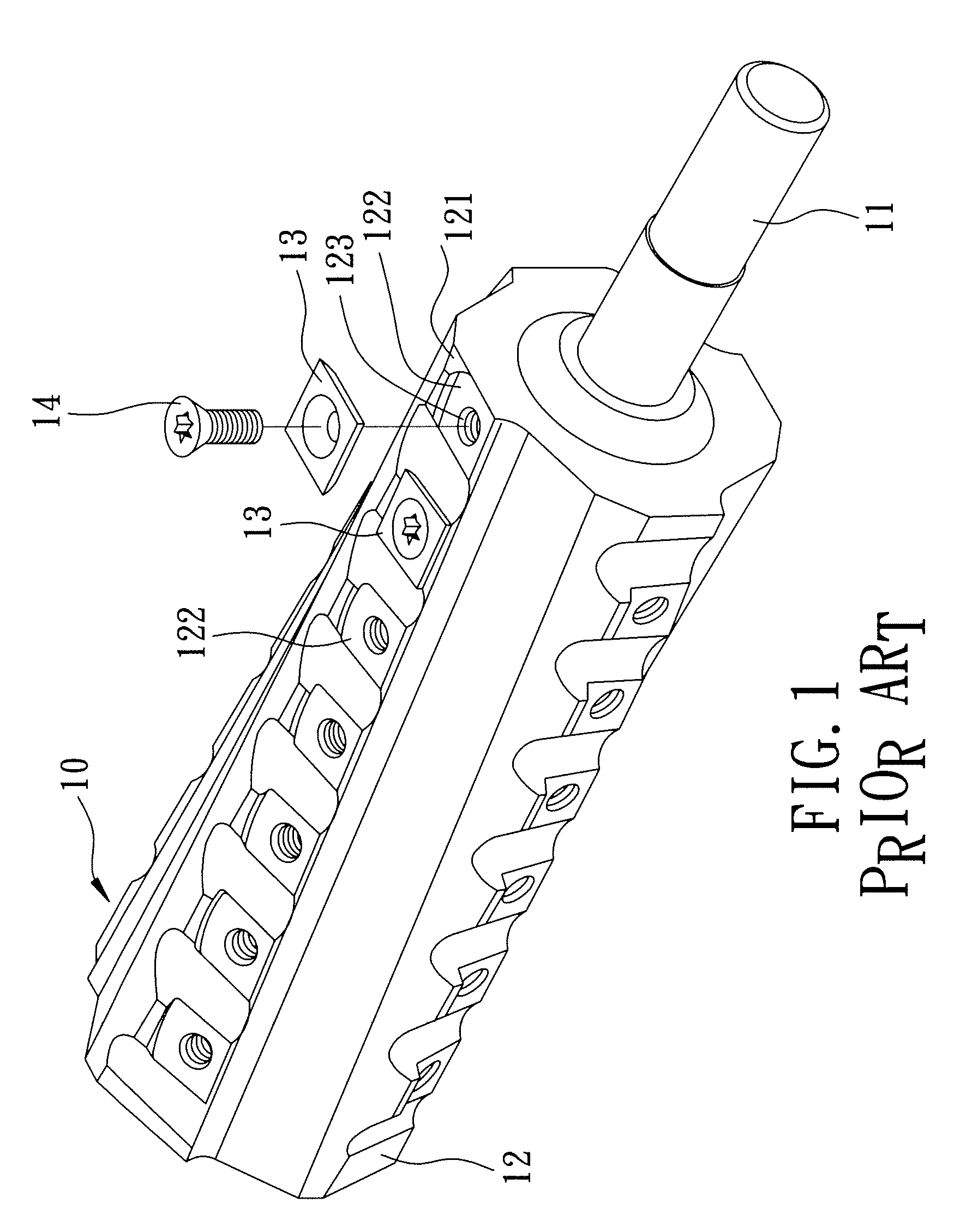
However, since the blade mounting blocks 122 are integrally formed with the shaft 12, are respectively formed with screw holes 123, and are required to be arranged in a spiral manner, fabrication of the shaft 12 is difficult, costly and time consuming.

Method used


Image

  • Cutter head assembly for a wood planing machine
  • Cutter head assembly for a wood planing machine
  • Cutter head assembly for a wood planing machine

Examples


Embodiment Construction

[0019]Before the present invention is described in greater detail, it should be noted that same reference numerals have been used to denote like elements throughout the specification.

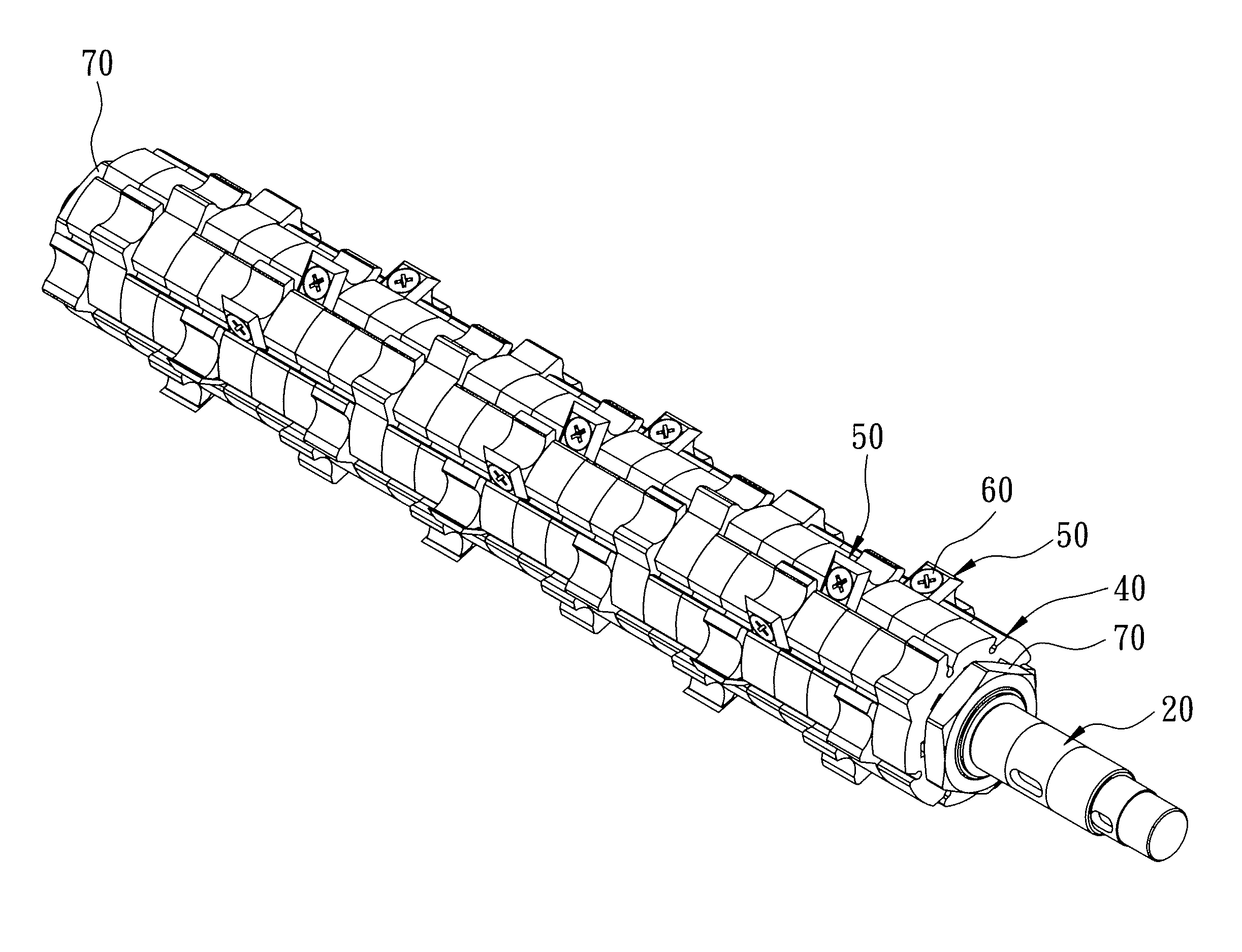
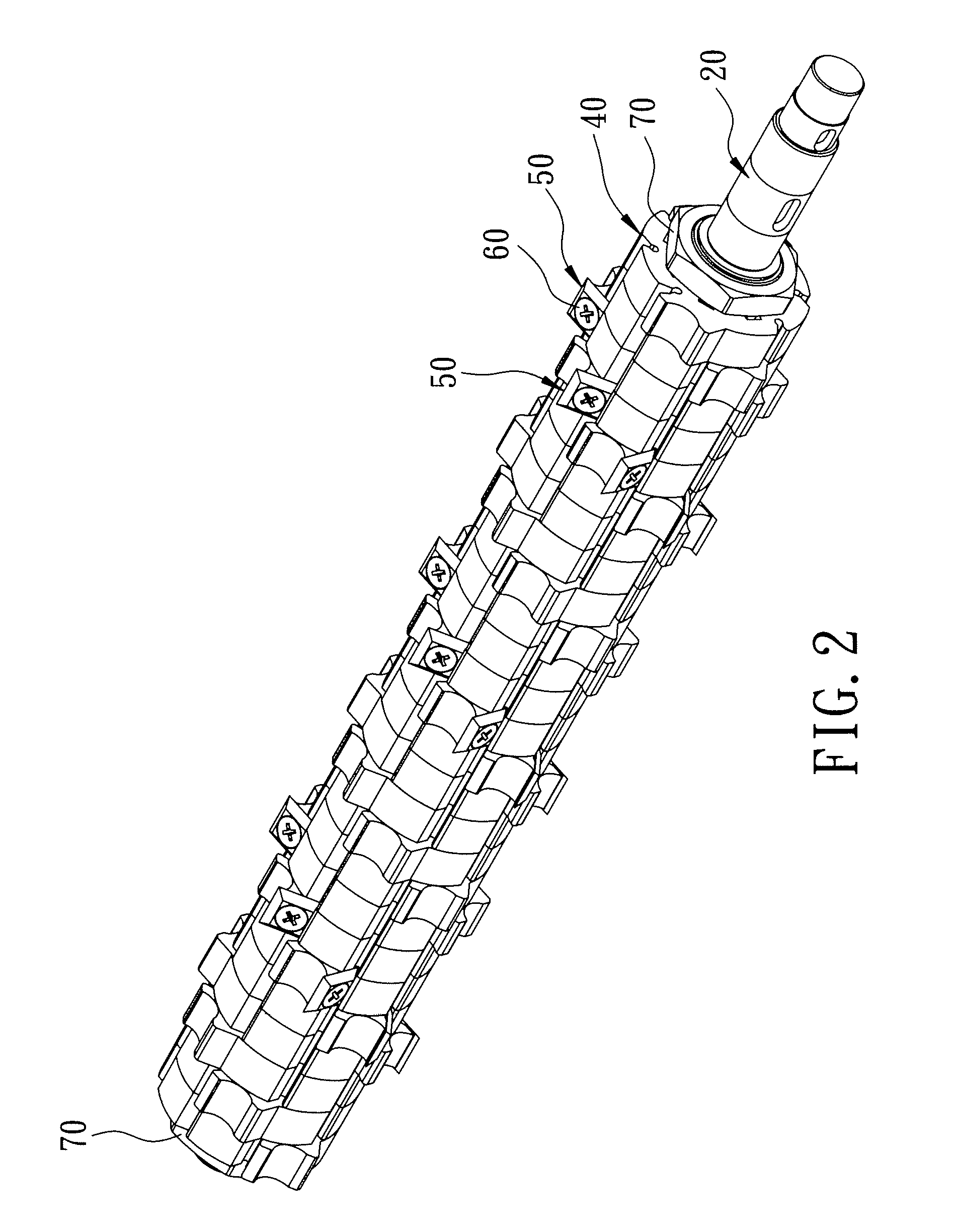
[0020]Referring to FIGS. 2 to 5, the first preferred embodiment of a cutter head assembly according to the present invention is adapted for use with a wood planing machine (not shown), and is shown to comprise a shaft 20, a plurality of cutter-mounting sleeve modules 40, a plurality of cutter modules 50, an angularly-variable positioning mechanism, and two fasteners 70.

[0021]The shaft 20 is elongated along an axis (I) in an axial direction, and has two ends 23 opposite to each other along the axis (I), and a mount segment 21 interposed between the ends 23.

[0022]Each of the cutter-mounting sleeve modules 40 (only one is shown in FIG. 4) has outer and inner wall surfaces 42,41 opposite to each other in radial directions. The outer wall surface 42 defines a slot 44 which extends towards the inner wall surf...


PUM


Abstract

A cutter head assembly for a wood planing machine includes a shaft, a plurality of cutter-mounting sleeve modules sleeved on the shaft, and a plurality of cutter modules respectively secured to the sleeve modules such that cutting edges of the cutter modules extend beyond outer wall surfaces of the sleeve modules. An angularly variable positioning mechanism includes an axially extending guiding member disposed on the mount segment, and a plurality of axially extending guided members disposed on inner wall surfaces of the sleeve modules to mate with the axially guiding member. By virtue of fitting engagement between the guiding member and a selected one of the guided member of each sleeve module that are sequentially sleeved onto the shaft, the cutting edges together define a cutting contour line that winds around the shaft.

Description

CROSS-REFERENCE TO RELATED APPLICATION[0001]This application claims priority of Taiwanese patent Application No. 097204764, filed on Mar. 20, 2008.BACKGROUND OF THE INVENTION[0002]1. Field of the Invention[0003]This invention relates to a cutter head assembly for a wood planing machine, more particularly to a modular cutter head assembly which constitutes a cutting contour line winding around a shaft.[0004]2. Description of the Related Art[0005]Referring to FIG. 1, a conventional cutter head assembly for a wood planing machine 10 is shown to have a spiral cutting contour which is constituted by a plurality of blade segments 13 so as to improve quality of wood products. The blade segments 13 are respectively secured to a plurality of blade mounting blocks 122 formed on an outer surrounding surface 121 of a shaft 12 by means of screw fasteners 14. The shaft 12 is driven by a transmitting axle 11 to rotate the blade segments 13 so as to perform a planing process. However, since the bla...

Claims


Application Information

Patent Timeline
Patent Type & Authority Applications(United States)
IPC IPC(8): B27G13/00
CPCB27G13/04B27G13/005
Inventor LIU, CHIN-YUAN
Owner SHINMAX IND
Learn More