
Independent sensing system for wind turbines

a wind turbine and independent technology, applied in the direction of rotors, vessel construction, marine propulsion, etc., can solve the problems of difficult and/or expensive access and/or monitoring to these large wind turbines, difficult measurement of particular operational parameters, including blade conditions and properties, and wired sensor systems, etc., to achieve flexibility in monitoring and operation, prevent or eliminate the propagation of lightning strikes, and facilitate the effect of efficient operation

Inactive Publication Date: 2009-09-17
GENERAL ELECTRIC CO
View PDF10 Cites 68 Cited by
  • Summary
  • Abstract
  • Description
  • Claims
  • Application Information

AI Technical Summary

Benefits of technology

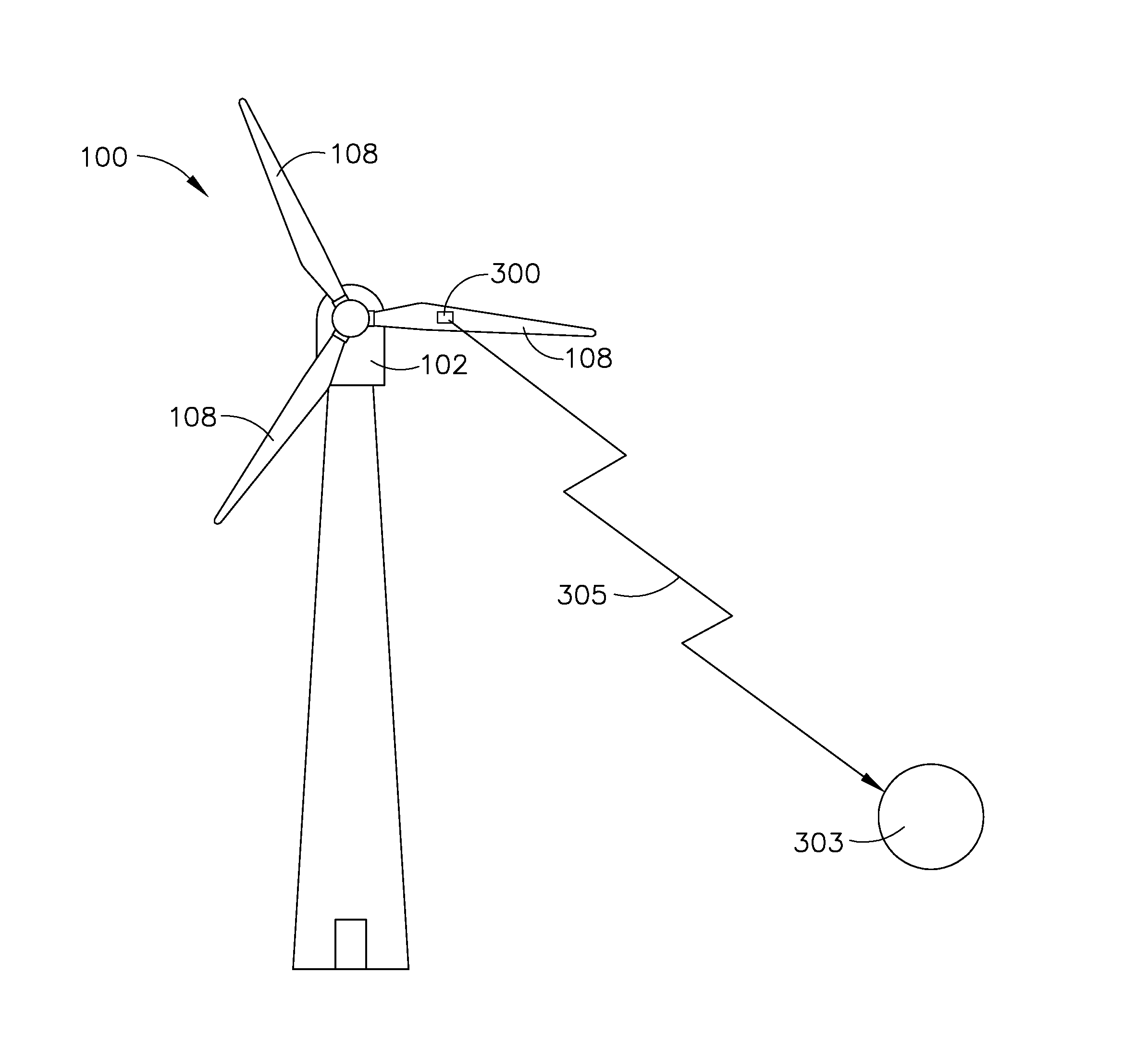
[0010]Embodiment of the disclosure include a device, system, and method based upon radio frequency, having an independent power supply, allowing for the wireless transmission of measurements taken by a sensor in or on a wind turbine component. The use of an independent power source and wireless transmission of information permits the wireless sensing device to provide information about operational parameters, while preventing or eliminating propagation of lightning strikes, particularly to the blades, to important wind turbine controls or components.
[0012]In addition, the system is inexpensive and may utilize wireless communication that permits flexibility in the monitoring and operation of the wind turbine.
[0013]Further, the system provides a method that is capable of taking into account blade parameters in the operation of the wind turbine to provide efficient operation.

Problems solved by technology

Access and / or monitoring to these large wind turbines can be difficult and / or expensive, particularly at wind turbine installations offshore.
In the past, measurements of particular operational parameters, including blade conditions and properties have been difficult.
In addition, wired sensor systems suffer from the drawback that lightning strikes may be conveyed along wires to more sensitive systems causing damage to the wind turbine and wind turbine systems.
Fiber optic systems for use in communication to sensors are not easily handled and are expensive.
Inclusion of these wires requires slip rings and increases part costs and maintenance costs.

Method used


Image

  • Independent sensing system for wind turbines
  • Independent sensing system for wind turbines
  • Independent sensing system for wind turbines

Examples


Embodiment Construction

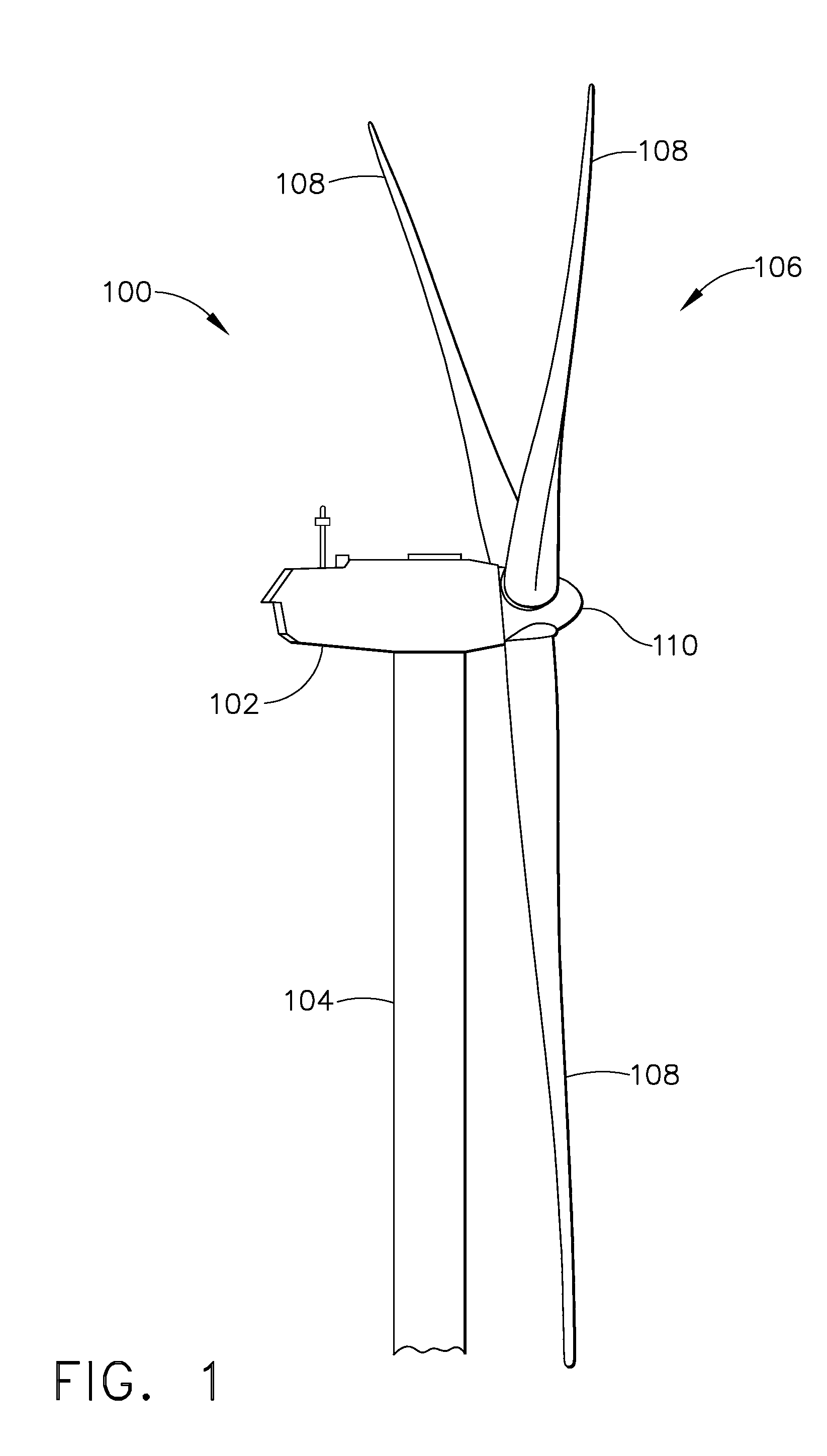
[0021]As shown in FIG. 1, a wind turbine 100 generally comprises a nacelle 102 housing a generator (not shown in FIG. 1). Nacelle 102 is a housing mounted atop a tower 104, only a portion of which is shown in FIG. 1. The height of tower 104 is selected based upon factors and conditions known in the art, and may extend to heights up to 100 meters or more. The wind turbine 100 may be installed on any terrain providing access to areas having desirable wind conditions. The terrain may vary greatly and may include, but is not limited to, mountainous terrain or offshore locations. Wind turbine 100 also comprises a rotor 106 that includes one or more rotor blades 108 attached to a rotating hub 110. Although wind turbine 100 illustrated in FIG. 1 includes three rotor blades 108, there are no specific limits on the number of rotor blades 108 required by the present disclosure.

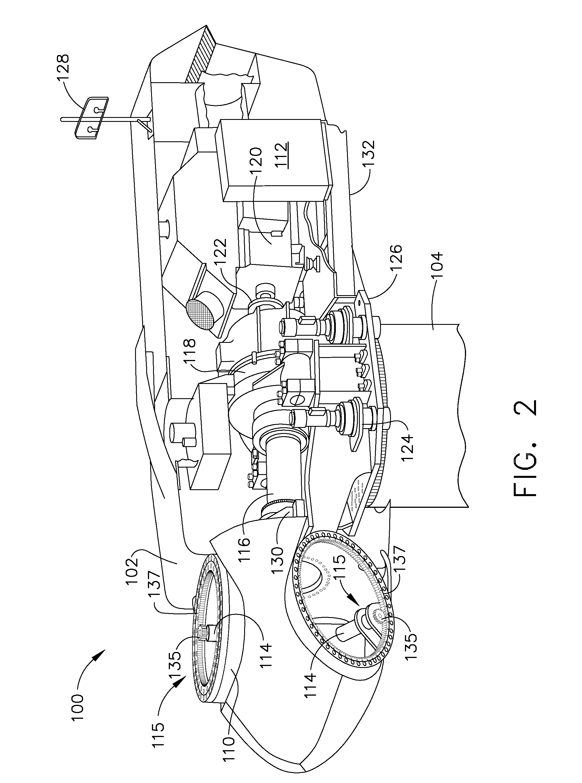
[0022]As shown in FIG. 2, various components are housed in nacelle 102 atop tower 104 of wind turbine 100. For exampl...


PUM


Abstract

A wireless sensing device for use in a wind turbine having a sensor capable of measuring one or more parameters for wind turbine operation. The sensing device also include a transmission device capable of wirelessly transmitting one or more signals corresponding to the one or more measured parameters to a controller. An independent power source is included to power the transmission device and the sensor. A method for system for operating and monitoring wind turbine operation are also disclosed.

Description

FIELD OF THE INVENTION[0001]The disclosure is directed to rotating device operations such as a wind turbine operation. In particular, the disclosure is directed to rotating device operations requiring the measurement of various parameters.BACKGROUND OF THE INVENTION[0002]Recently, wind turbines have received increased attention as environmentally safe and relatively inexpensive alternative energy sources. With this growing interest, considerable efforts have been made to develop wind turbines that are reliable and efficient.[0003]Generally, a wind turbine includes a rotor having multiple blades. The rotor is mounted to a housing or nacelle, which is positioned on top of a truss or tubular tower. Utility grade wind turbines (i.e., wind turbines designed to provide electrical power to a utility grid) can have large rotors (e.g., 30 or more meters in length). In addition, the wind turbines are typically mounted on towers that are at least 60 meters in height. Access and / or monitoring t...

Claims


Application Information

Patent Timeline
Patent Type & Authority Applications(United States)
IPC IPC(8): F03D11/00F03D7/02
CPCF03D11/0033F03D11/0091F03D7/047Y02E10/723Y02E10/722F03D80/30F03D17/00Y02E10/72
Inventor MENKE, DETLEF
Owner GENERAL ELECTRIC CO
Learn More