
Storm curtain side retention system

a curtain and side edge technology, applied in the field of curtain side retention system, can solve the problems of disfiguring the exterior of the structure, and affecting the appearance of the structur

Inactive Publication Date: 2009-09-17
WAYNE DALTON CORP
View PDF30 Cites 36 Cited by
  • Summary
  • Abstract
  • Description
  • Claims
  • Application Information

AI Technical Summary

Benefits of technology

[0007]It is thus an object of the present invention to provide a storm curtain which can be used to cover an opening in a structure thereby protecting the structure.
[0009]It is an object of another aspect of the present invention to provide an assembly, as above, which may eliminate the need to lock the fabric in the sill area at the bottom of the opening.

Problems solved by technology

Otherwise, if the high winds or wind-borne debris breaches the integrity of the structure by destroying a window or door, severe damage to the structure can be expected.
However, this “boarding up” procedure is not only time consuming, when time is usually of the essence, but also can disfigure the exterior of the structure upon frequent installation and removal.
Moreover, the plywood solution creates dark environments, and the weight, size, and limited shapes of the sheets often make deployment difficult, especially in windy conditions.
In addition, plywood deteriorates with time, and storing and maintaining an inventory of plywood sheets can be problematic.
However, these devices are not only costly, but also the lateral edges thereof do not provide a proper seal.

Method used


Image

  • Storm curtain side retention system
  • Storm curtain side retention system
  • Storm curtain side retention system

Examples


Embodiment Construction

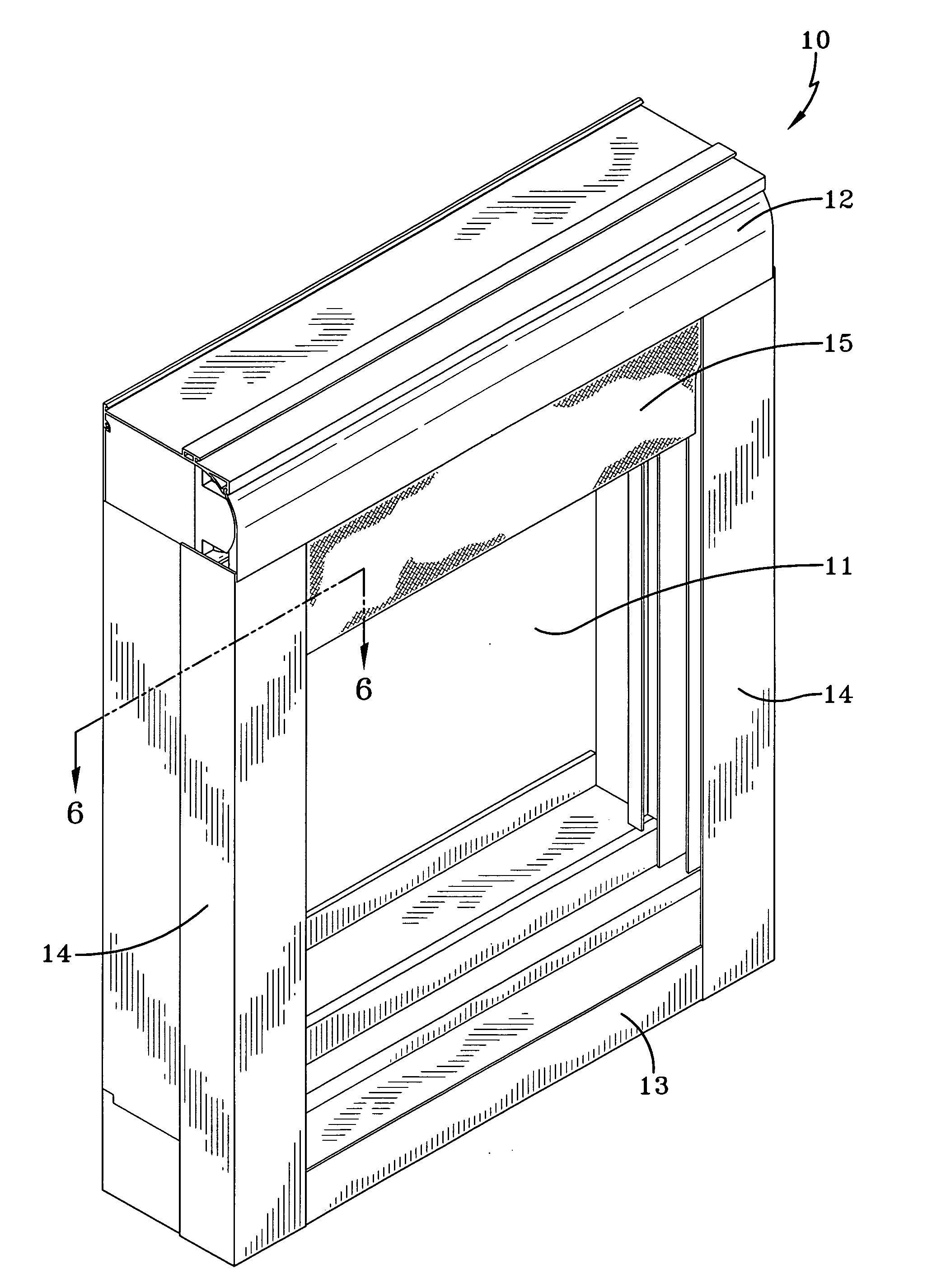
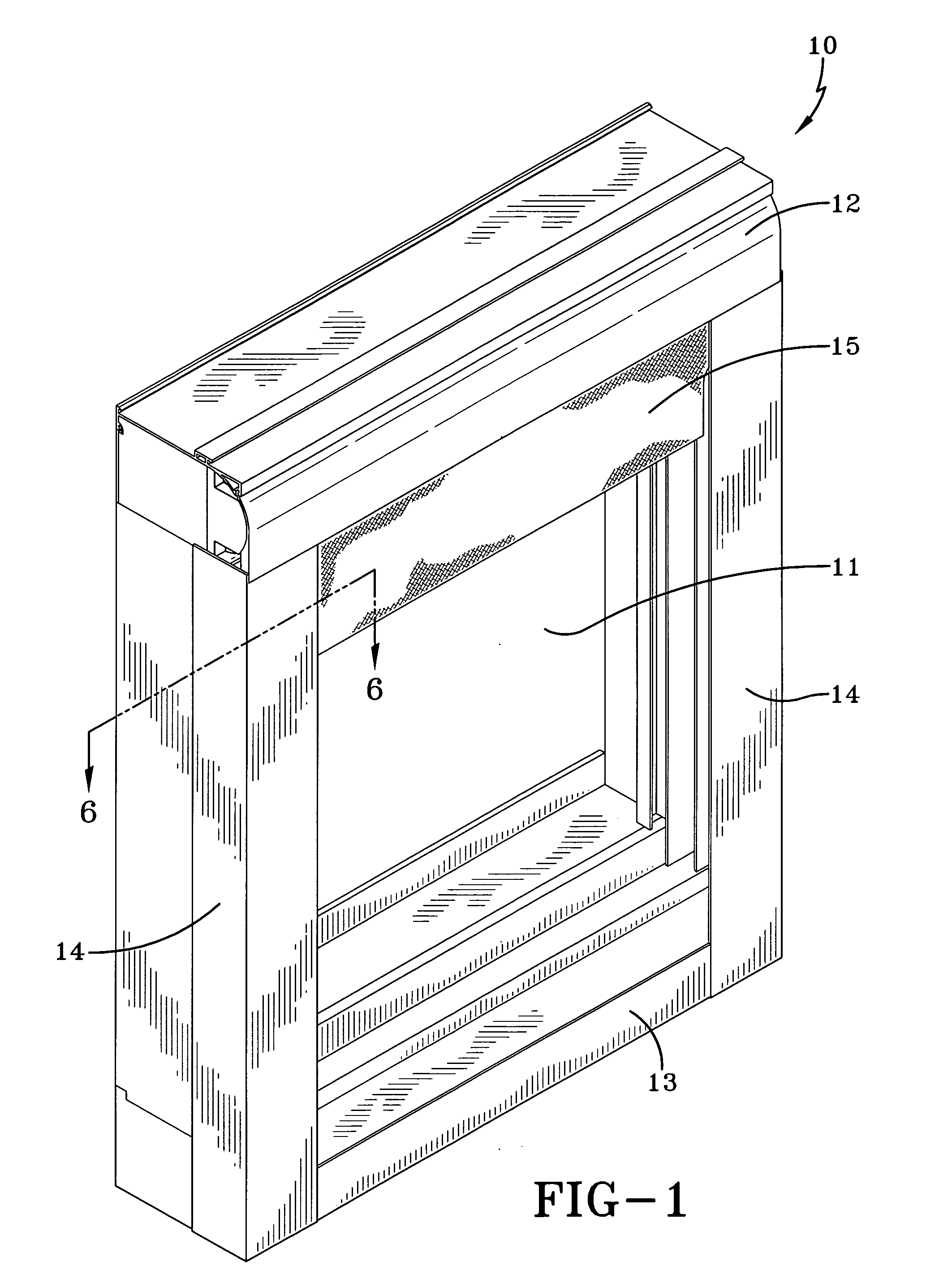
[0025]A storm curtain assembly made in accordance with the present invention is indicated generally by the numeral 10 in FIG. 1 and is adapted to be used to cover an opening, such as a window 11 of a structure. Assembly 10 can be positioned on the outside of the structure or on the inside thereof and includes an upper header 12 which extends across the top of window 11 and a lower sill 13 which extends across the bottom of the window 11. Laterally spaced side rails 14 extend vertically between the lateral edges of header 12 and sill 13.

[0026]As shown in FIG. 4, a curtain 15 has an upper end 16 longitudinally spaced from a lower end 17 and has opposed laterally spaced side edges 18. Curtain 15 can be made of any suitable material having a strength to protect opening and is preferably formed of a fabric material as disclosed in U.S. patent application Ser. No. 11 / 190,114 to which reference is made for whatever details may be necessary to fully understand the present invention. The upp...


PUM


Abstract

A curtain assembly (10) to cover and protect an opening in a structure, such as a window (11), includes side rails (14) which extend between a header (12) and a sill (13). A roller (19) is positioned in the header (12) and carries a fabric curtain (15). Tabs (20) extend outwardly from the lateral edges (18) of the curtain (15), and at least some of the tabs (20) carry at least one retention member (21, 22 or 23). Tabs (15) and the retention members (21, 22 or 23) are received in a compartment (39) in the side rails (14). Flap walls (40, 52) form a portion of the compartments (39) and are spaced from each other. The curtain (15) can extend through the space (56) but the retention members (21, 22 or 23) cannot. As a result, upon impact against the curtain, the retention members (21, 22 or 23) engage the flap walls (40, 52) which engage the curtain (15) and the curtain (15) is maintained in the side rails (14). Because the tabs (20) extend outwardly beyond the lateral edges of the roller (19), no additional space is taken up by the retention members (21, 22 or 23) when the curtain (15) is rolled up on the roller (19).

Description

TECHNICAL FIELD[0001]This invention relates to a curtain assembly which protects a building from damage due to the breach of an opening in the building caused by high winds and wind-borne debris oftentimes present during storm conditions. More specifically, this invention relates to a system for maintaining the side edges of a curtain in the side rails of the assembly.BACKGROUND ART[0002]In geographic areas which are prone to having high wind events, such as hurricanes and the like, the need exists for the protection of openings, such as windows and doors, in buildings. Otherwise, if the high winds or wind-borne debris breaches the integrity of the structure by destroying a window or door, severe damage to the structure can be expected.[0003]One type of simple protection device involves the use of a sheet of plywood which can be attached to the structure so as to cover the openings thereof. However, this “boarding up” procedure is not only time consuming, when time is usually of the...

Claims


Application Information

Patent Timeline
Patent Type & Authority Applications(United States)
IPC IPC(8): E06B9/58E06B9/00
CPCE06B9/581
Inventor MULLET, WILLIS J.HAND, RICHARD S.BRUNK, DARRIN W.
Owner WAYNE DALTON CORP
Learn More