
Bill Discriminating And Counting Apparatus

a bill discrimination and counting technology, applied in the field of bill discrimination and counting apparatus, can solve the problems of conventional apparatus having a problem on working efficiency, the process initially performed by one of the tellers is wasted, and the other teller cannot perform the counting and storing operation with the apparatus, so as to reduce the total cost of introducing the apparatus and enhance the efficiency of the bill discrimination and counting work.

Active Publication Date: 2009-09-10
GLORY KOGYO KK
View PDF12 Cites 7 Cited by
  • Summary
  • Abstract
  • Description
  • Claims
  • Application Information

AI Technical Summary

Benefits of technology

[0013]In view of the foregoing, an object of the invention is to provide a bill discriminating and counting apparatus in which the two operators can commonly use the one apparatus, and thereby the efficiency in the bill discriminating and counting work is enhanced, and total cost of introducing the apparatus is decreased.MEANS FOR SOLVING THE PROBLEMS

Problems solved by technology

However, when the apparatus is continuously set in the state occupied by one of the tellers until one transaction is ended, the other teller cannot perform the counting and storing operation with the apparatus, even if the counting and storing operation is interrupted by some reason.
When the other teller uses the apparatus, because it is necessary that the interrupted process be reset to switch the apparatus to the state occupied by the other teller, the process initially performed by one of the tellers is wasted.
Therefore, the conventional apparatus has a problem on working efficiency.
Therefore, design is not made such that the two operators can commonly use the one apparatus.
Accordingly, in a store or a financial institution in which the bill discriminating and counting apparatus is used, it is necessary that the number of bill discriminating and counting apparatus be required as many operators as there are, which results in a problem from the standpoint of capital investment.

Method used


Image

  • Bill Discriminating And Counting Apparatus
  • Bill Discriminating And Counting Apparatus
  • Bill Discriminating And Counting Apparatus

Examples


Embodiment Construction

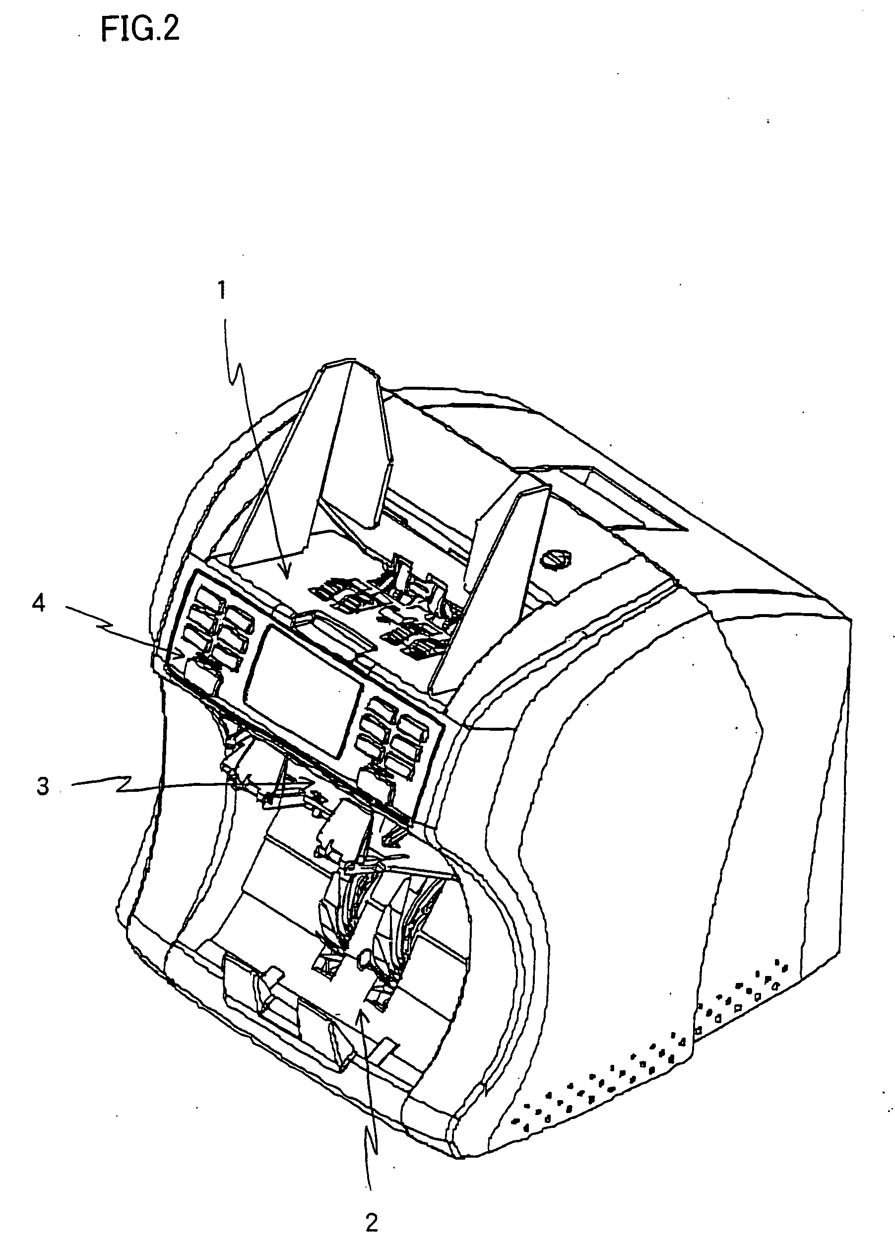
[0020]The present invention relates to a bill discriminating and counting apparatus having a function in which two operators can commonly operate one apparatus. That is, two pairs of a process instruction button for instructing start / stop of a discriminating and counting process and an approval button for approving counting result are provided, two independent storage areas are provided in a storage area in which the counting result is stored, the counting result is stored in the corresponding storage area while each storage area is associated with the pair of the process instruction button and the approval button, and two operators can commonly use the one bill discriminating and counting apparatus by providing occupation switching means for switching an occupation state of the bill discriminating and counting apparatus and occupation state display means for displaying a current occupation state.

[0021]The bill discriminating and counting apparatus according to the invention will be...


PUM


Abstract

The present invention relates to a bill discriminating and counting apparatus having a function in which two operators can commonly operate the one apparatus. That is, two pairs of a process instruction button for instructing start / stop of a discriminating and counting process and an approval button for approving counting result are provided, two independent storage areas are provided in a storage area in which the counting result is stored, the counting result is stored in the corresponding storage area while each storage area is associated with the pair of the process instruction button and the approval button, and two operators can commonly use the one bill discriminating and counting apparatus by providing occupation switching means for switching an occupation state of the bill discriminating and counting apparatus and occupation state display means for displaying a current-occupation state.

Description

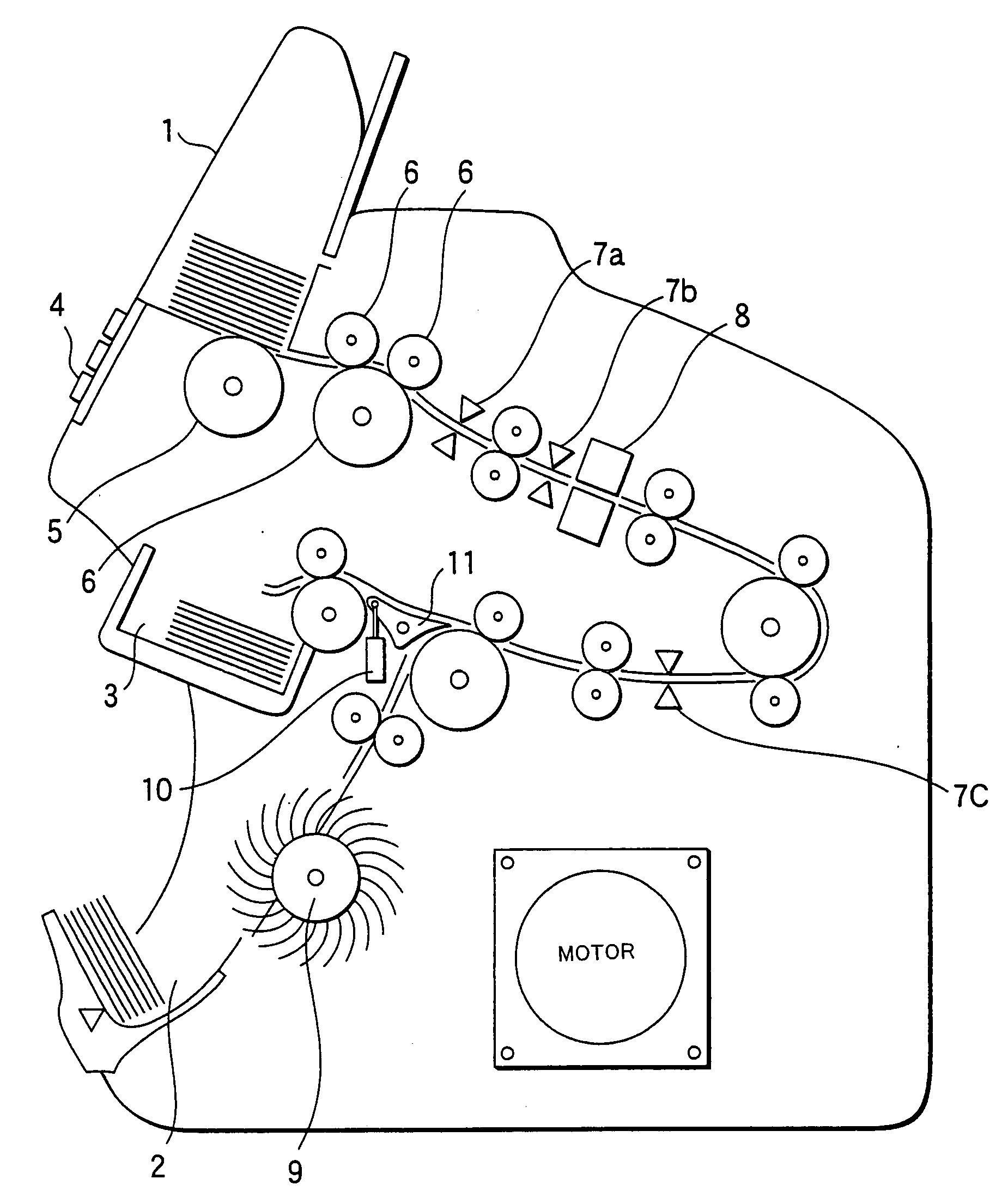
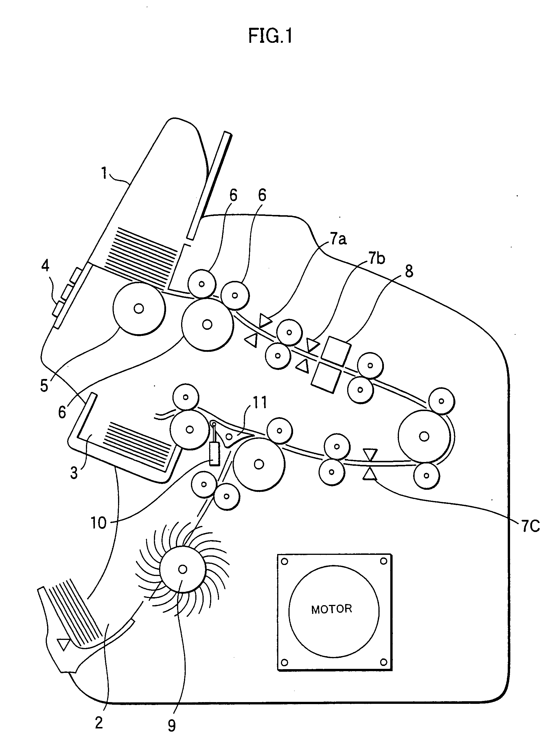
TECHNICAL FIELD[0001]The present invention relates to a bill discriminating and counting apparatus which discriminates a denomination of a bill received through a hopper while counting a total amount of the received bills or the number of bills in each denomination, particularly to the bill discriminating and counting apparatus having a function in which two operators can operate one apparatus.BACKGROUND ART[0002]There is a well known bill discriminating and counting apparatus, in which bills having mixed denominations are collectively received from a hopper, the bills are fed and carried one by one, the bills are counted while the denomination and authenticity of the bills are discriminated, and the total amount of the normal bill or the number of bills in each denomination is counted and displayed (for example, see Japanese Patent Application Laid-Open No. 2003-296801).[0003]A structure and an operation of a conventional bill discriminating and counting apparatus will be described...

Claims


Application Information

Patent Timeline
Patent Type & Authority Applications(United States)
IPC IPC(8): G07D3/00
CPCG07D11/0084B65H2701/1912G07D7/00G07F7/04G07D7/20G07D11/0081G07D7/12G07D11/50G07D11/40
Inventor MATSUURA, SHINJINUMATA, TOSHIOMORINO, HAJIMEMATSUI, SHINJI
Owner GLORY KOGYO KK
Learn More