
Controlling Spatial Audio Coding Parameters as a Function of Auditory Events

a spatial audio and coding parameter technology, applied in the field of audio encoding methods and apparatus, can solve the problems of computational complexity, specialized techniques for sound separation, and the practicability of auditory scene analysis, and achieve the effect of reducing the number of instruments and reducing the number of nois

Inactive Publication Date: 2009-09-03
DOLBY LAB LICENSING CORP
View PDF16 Cites 77 Cited by
  • Summary
  • Abstract
  • Description
  • Claims
  • Application Information

AI Technical Summary

Benefits of technology

The present invention is an audio encoder that receives multiple input audio channels and generates output channels and parameters that describe the desired spatial relationships among the channels. The encoder detects changes in signal characteristics over time in the input channels and identifies these changes as auditory event boundaries, which are the boundaries between segments of audio that are perceived as separate and distinct. The parameters are generated at least partly in response to the auditory events and the degree of change in signal characteristics associated with the boundaries. The invention can be implemented in both analog and digital domains. The technical effect of the invention is improved spatial sound perception for the listener by accurately reproducing the spatial characteristics of the audio.

Problems solved by technology

In addition, U.S. Pat. No. 6,002,776 to Bhadkamkar, et al, Dec. 14, 1999 cites publications dating back to 1976 as “prior art work related to sound separation by auditory scene analysis.” However, the Bhadkamkar, et al patent discourages the practical use of auditory scene analysis, concluding that “[t]echniques involving auditory scene analysis, although interesting from a scientific point of view as models of human auditory processing, are currently far too computationally demanding and specialized to be considered practical techniques for sound separation until fundamental progress is made.”

Method used


Image

  • Controlling Spatial Audio Coding Parameters as a Function of Auditory Events
  • Controlling Spatial Audio Coding Parameters as a Function of Auditory Events
  • Controlling Spatial Audio Coding Parameters as a Function of Auditory Events

Examples


Embodiment Construction

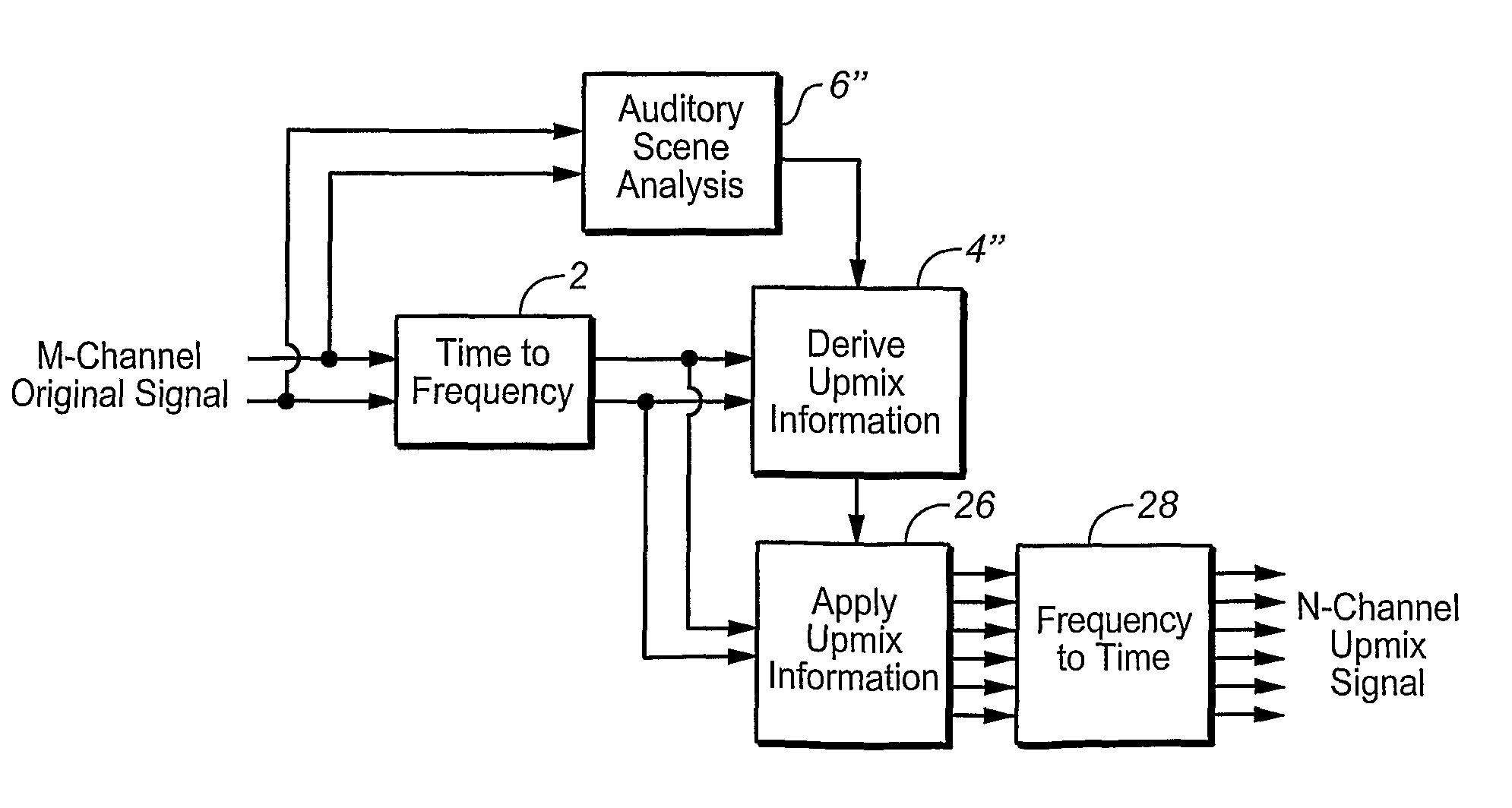
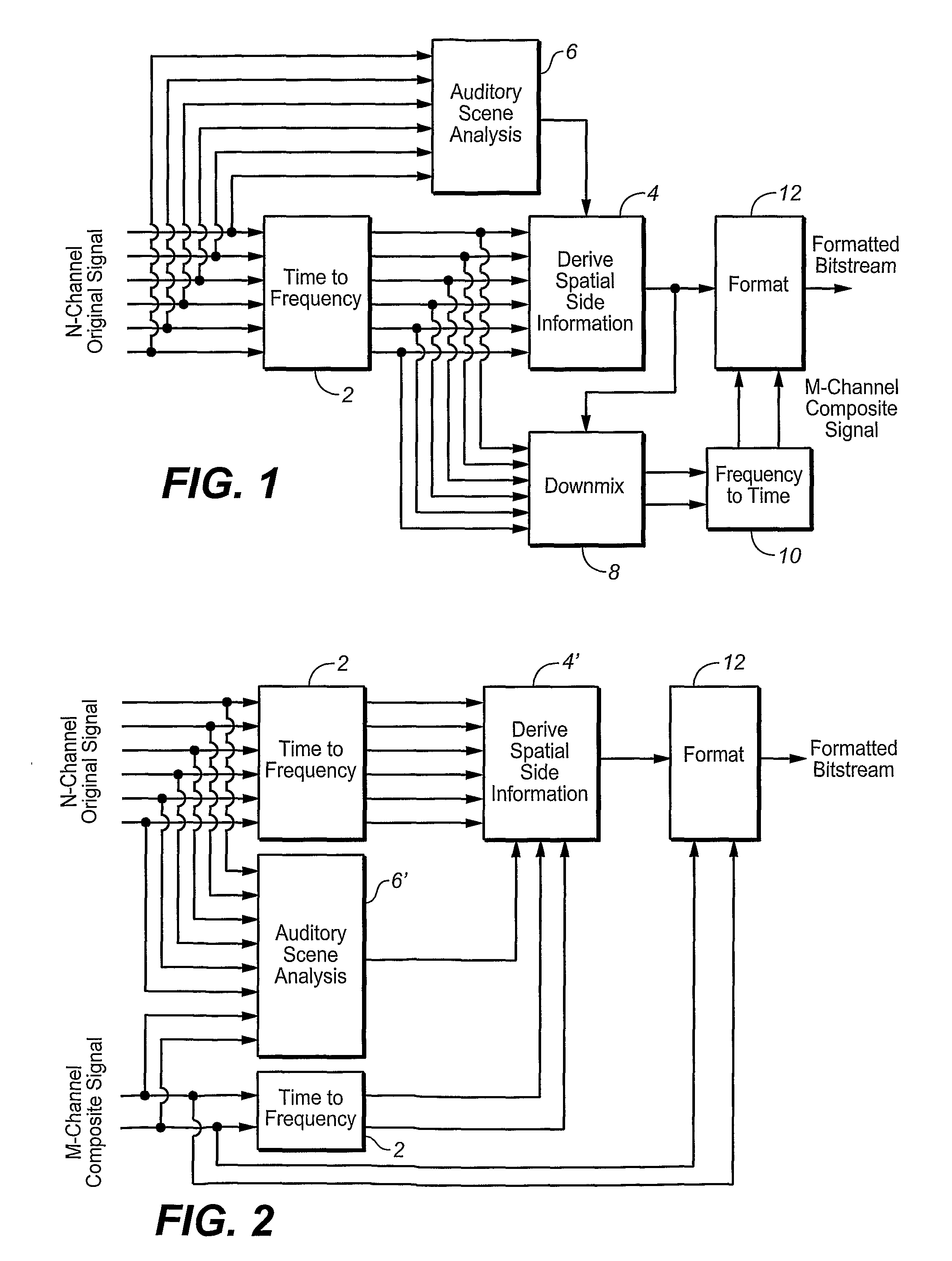
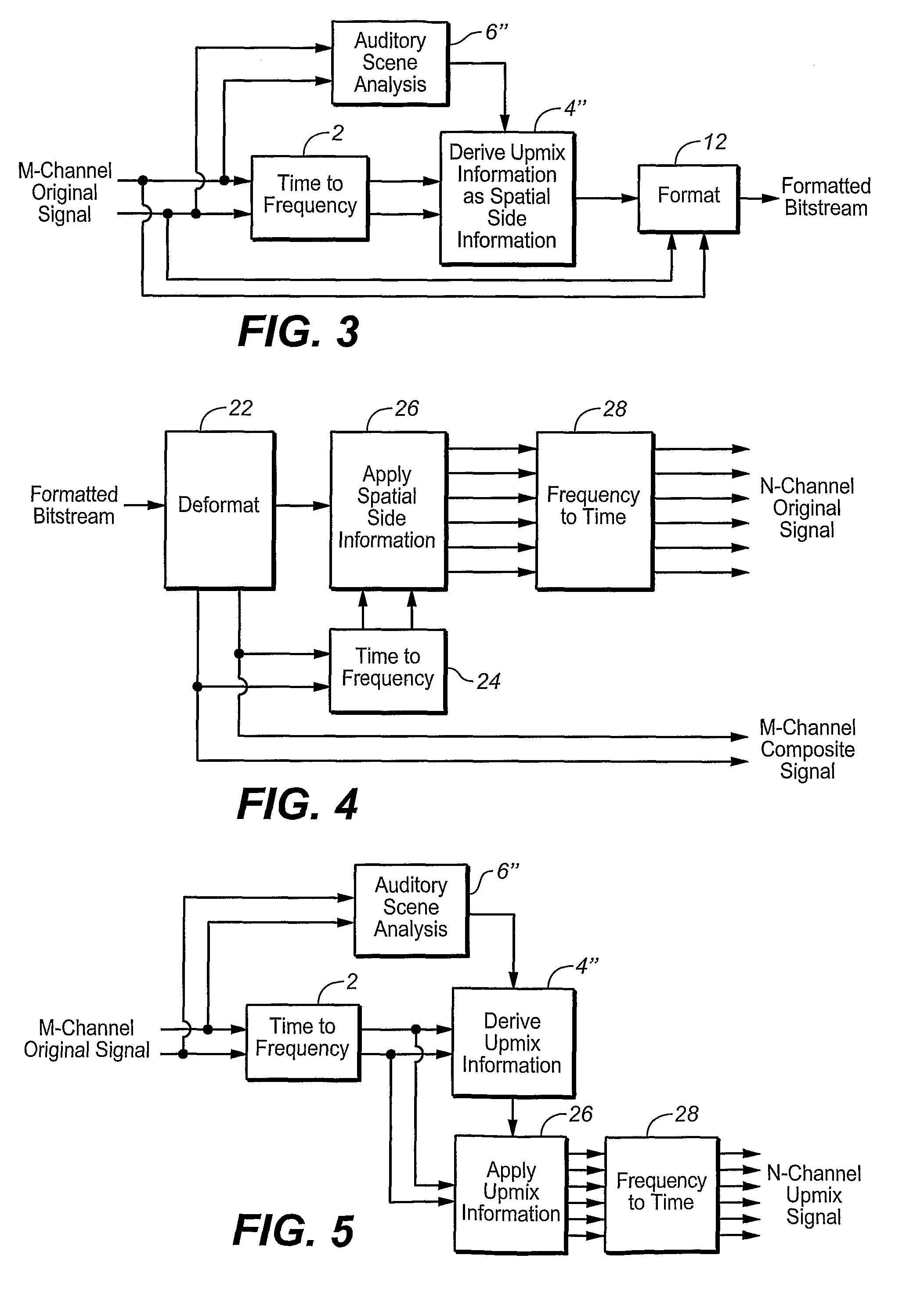
[0022]Some examples of spatial encoders in which aspects of the invention may be employed are shown in FIGS. 1, 2 and 3. Generally, a spatial coder operates by taking N original audio signals or channels and mixing them down into a composite signal containing M signals or channels, where M<N. Typically N=6 (5.1 audio), and M=1 or 2. At the same time, a low data rate sidechain signal describing the perceptually salient spatial cues between or among the various channels is extracted from the original multichannel signal. The composite signal may then be coded with an existing audio coder, such as an MPEG-2 / 4 AAC encoder, and packaged with the spatial sidechain information. At the decoder the composite signal is decoded, and the unpackaged sidechain information is used to upmix the composite into an approximation of the original multichannel signal. Alternatively, the decoder may ignore the sidechain information and simply output the composite signal.

[0023]The spatial coding systems pr...


PUM


Abstract

An audio encoder or encoding method receives a plurality of input channels and generates one or more audio output channels and one or more parameters describing desired spatial relationships among a plurality of audio channels that may be derived from the one or more audio output channels, by detecting changes in signal characteristics with respect to lime in one or more of the plurality of audio input channels, identifying as auditory event boundaries changes in signal characteristics with respect to lime in the one or more of the plurality of audio input channels, an audio segment between consecutive boundaries constituting an auditory event in the channel or channels, and generating all or some of the one or more parameters al least partly in response to auditory events and / or the degree of change in signal characteristics associated with the auditory event boundaries. An auditory-event-responsive audio upmixer or upmixing method is also disclosed.

Description

TECHNICAL FIELD[0001]The present invention relates to audio encoding methods and apparatus in which an encoder downmixes a plurality of audio channels to a lesser number of audio channels and one or more parameters describing desired spatial relationships among said audio channels, and all or some of the parameters are generated as a function of auditory events. The invention also relates to audio methods and apparatus in which a plurality of audio channels are upmixed to a larger number of audio channels as a function of auditory events. The invention also relates to computer programs for practicing such methods or controlling such apparatus.BACKGROUND ARTSpatial Coding[0002]Certain limited bit rate digital audio coding techniques analyze an input multichannel signal to derive a “downmix” composite signal (a signal containing fewer channels than the input signal) and side-information containing a parametric model of the original sound field. The side-information (“sidechain”) and c...

Claims


Application Information

Patent Timeline
Patent Type & Authority Applications(United States)
IPC IPC(8): G10L21/00
CPCG10L19/008H04S2420/03H04S3/008G10L19/08
Inventor SEEFELDT, ALAN JEFFREYVINTON, MARK STUART
Owner DOLBY LAB LICENSING CORP
Learn More