
Focus actuated vergence

a focus and vergence technology, applied in the field of parallax correction systems, can solve the problems of consuming additional electrical power, affecting the operation of battery operated devices, and requiring additional computations for added electronic image processing,

Active Publication Date: 2009-08-20
BAE SYST INFORMATION & ELECTRONICS SYST INTERGRATION INC
View PDF10 Cites 14 Cited by
  • Summary
  • Abstract
  • Description
  • Claims
  • Application Information

AI Technical Summary

Benefits of technology

The present invention provides a system and method for verging images from multiple cameras. The system includes a first camera with a focus adjustment, a second camera at a distance from the first camera, and a comparator to compare the images and determine the vergence data. The processor then aligns and superimposes the images. The focus adjustment can be made using a focus dial or a position sensor. The lens is disposed in a lens block slideably disposed within a lens housing, and the position sensor can be a Hall sensor, potentiometer, or spring. The method compensates for parallax error and velocity induced misregistration. The position of the lens block can be determined using a sensor or a tension meter. The technical effects of the invention include improved image quality and more precise alignment of multiple images.

Problems solved by technology

This problem is not unlike that of boresighting a rifle sight to a gun.
A disadvantage of this approach is that the added electronic image processing requires additional computation and consequently will consume additional electrical power.
This undesirable in a lightweight, battery operated device.
Most of the computational effort (and power consumption) is related to determining the amount of offset between the two images.
In addition, due to changing environmental conditions there will be circumstances whereby the image contrast from one camera or the other may be inadequate to perform a good correlation.
For example, on a very dark night, a visible camera may provide a dark, low contrast, barely useful image, while the thermal image may provide a bright, high contrast image.
A cross-correlation may not work well in this case since the image quality would be poor in one of the images.
So, automatic correlation fails in that case.
Another issue arising from such an approach is that, like auto-focus in conventional cameras, auto registration can only guess at what region of the image the user wants to correct for parallax, or operate in a predefined region of the image (e.g. the center).

Method used


Image

  • Focus actuated vergence
  • Focus actuated vergence
  • Focus actuated vergence

Examples


examples

Ranging and GPS Coordinate Extraction

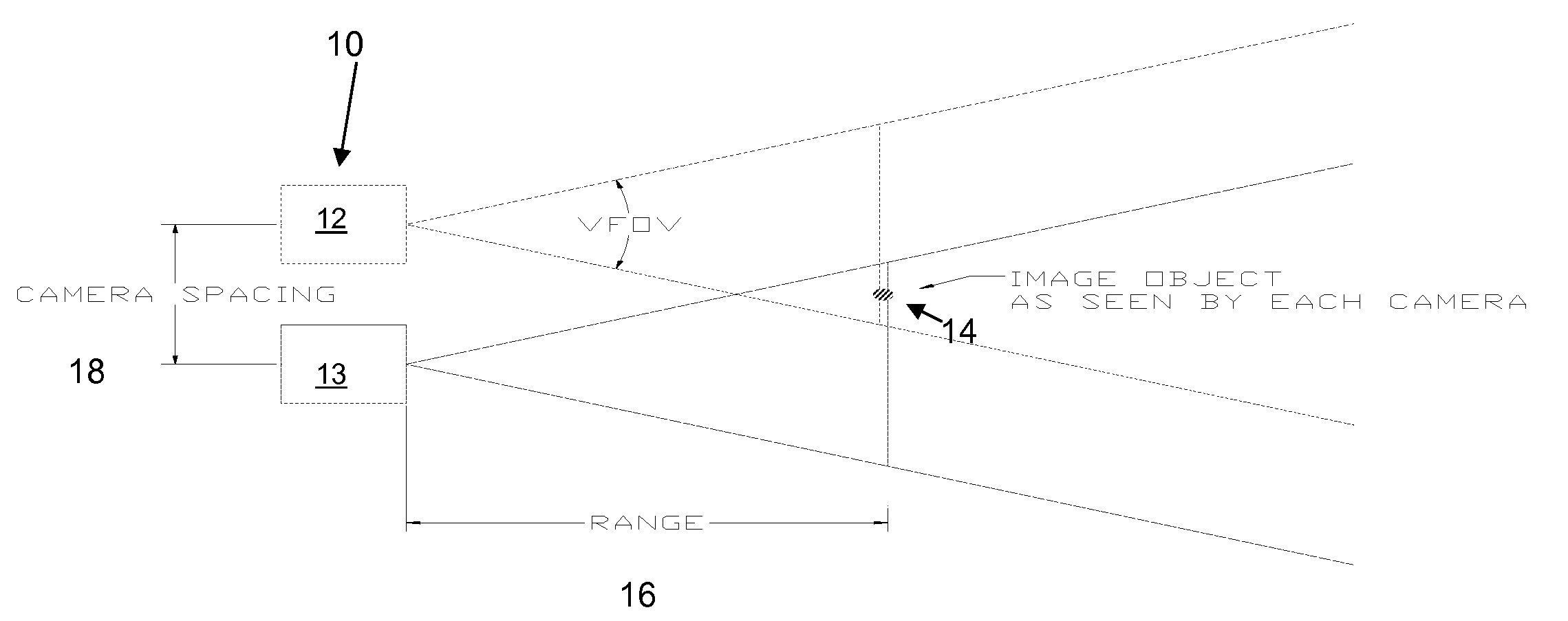
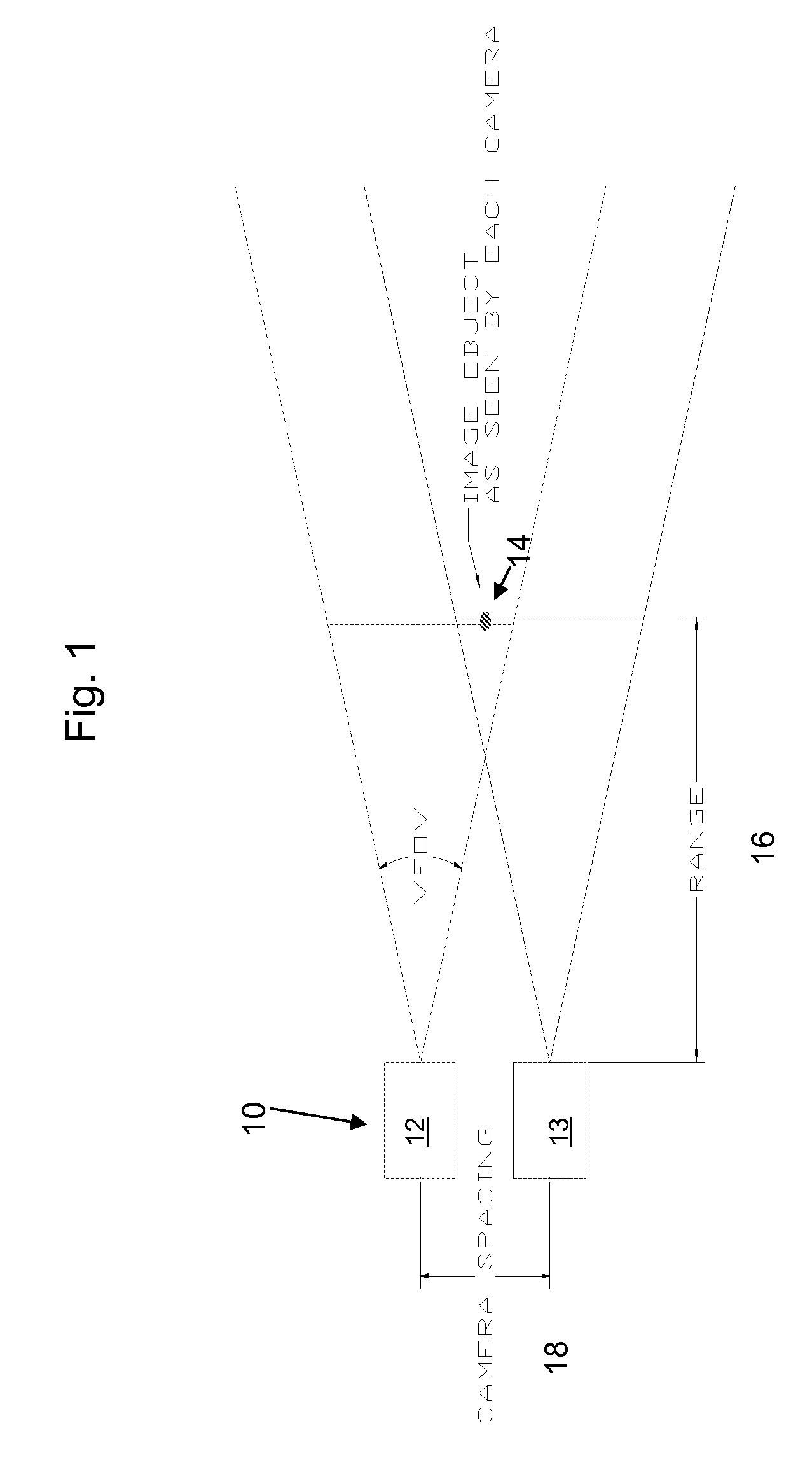
[0063]As illustrated in FIG. 1, the amount of image offset to be introduced into an acquired image to achieve pixel correspondence to imagery acquired from another camera can be determined if the separation distance between the cameras and the range the object is known. Since the separation distance is typically fixed by the specific geometry of the system, and an indication of range developed from focus control or lens position, the amount of image offset can be uniquely determined. This approach avoids reliance on complex image processing techniques to achieve this result, with an attendant reduction in associated power consumption. In addition, the need for a separate vergence adjustment control is eliminated, simplifying the user interface.

[0064]An extension of this concept can be used to derive Global Positioning System (GPS) coordinates of objects in the field of view based on the amount of parallax-induced image offset observed between cor...


PUM


Abstract

A system is disclosed for the vergence of images from a plurality of cameras, the system having: an first camera; a second camera disposed at some distance from that first camera; a focus adjustment whereby the focus of the first camera can be adjusted by a user; the focus adjustment being configured with a range finder whereby the distance from the first camera to a target is ascertained; a look up chart wherein divergence distance of images generated from the first camera from images of the second camera are provided for pre-calculated ranges; a processor whereby said images generated by the first camera are superimposed on the images generated by the second camera by the divergence distance determined from the lookup.

Description

STATEMENT OF GOVERNMENT INTEREST[0001]Portions of the present invention may have been made in conjunction with Government funding under contract number Contract No.: W91CRB-07-C-0098 Digital Enhanced Night Vision Goggle (D) (ENVG(D)), and there may be certain rights to the Government.RELATED APPLICATIONSField of the Invention[0002]The invention relates to parallax correction systems, and more particularly, to a system and method for correcting parallax in the overlap of images from a multiple camera array.BACKGROUND OF THE INVENTION[0003]Night vision goggle systems are evolving to incorporate multiple imagers (cameras), such that the output video streams from each imager may be selectively fused into an output video stream. This video stream is then presented to the user, typically on a microdisplay as viewed through monocular optics. Alternative embodiments of this basic architecture are possible.[0004]Typically each imager consists of a set of optics, a focal plane and associated ...

Claims


Application Information

Patent Timeline
Patent Type & Authority Applications(United States)
IPC IPC(8): H04N13/02
CPCH04N5/23212H04N5/2628H04N13/0296H04N13/0239H04N13/0022H04N13/128H04N13/296H04N13/239H04N23/67
Inventor FEDA, FRANCIS M
Owner BAE SYST INFORMATION & ELECTRONICS SYST INTERGRATION INC
Learn More