Imaging apparatus
- Summary
- Abstract
- Description
- Claims
- Application Information
AI Technical Summary
Benefits of technology
Problems solved by technology
Method used
Image


Examples
first embodiment
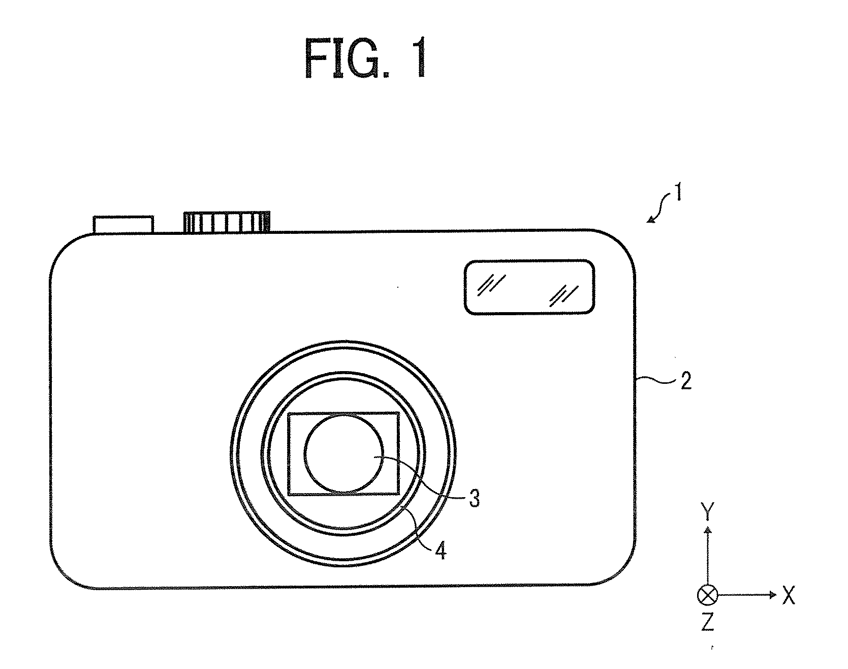
[0026]FIG. 1 shows an example of a digital camera as an imaging apparatus according to a first embodiment of the present invention.
[0027]This digital camera includes an image stabilization function for compensating camera shake by moving an image pickup device in a plane perpendicular to a direction in which an optical axis of a photographing lens system extends. The image pickup device will be described later.
[0028]As shown in FIG. 1, the digital camera 1 includes a camera main body 2 and a lens barrel 4 provided in the front of the camera main body 2. A photographing lens system 3 that photographs an unillustrated subject is provided inside the lens barrel 4. The lens barrel 4 is configured so as to be movable between its collapsed position and image pickup standby position in a direction in which an optical axis of the photographing lens system 3 extends. The collapsed position causes the lens barrel 4 to be housed inside the camera main body 2. The image pickup standby position ...
second embodiment
[0071]The digital camera 1 according to the first embodiment has the configuration in which the magnetic metal member 11 is adhered to the center portion in the rear of the CCD 8. By contrast, the digital camera 1 according to the second embodiment has a configuration in which a permanent magnet 28 is adhered to the center portion in the rear of the CCD 8 as shown in FIG. 10. The rest of the configuration according to the second embodiment is the same as that according to the first embodiment. For this reason, duplicated descriptions will be omitted.
[0072]By causing an electric current with a predetermined polarity to be applied to the electromagnetic coil 25, the digital camera 1 according to the second embodiment is capable of generating an attractive magnetic force F between the electromagnetic coil 25 and the permanent magnet 28 in the same manner as the digital camera 1 according to the first embodiment is. In this manner, the digital camera 1 according to the second embodiment...
third embodiment
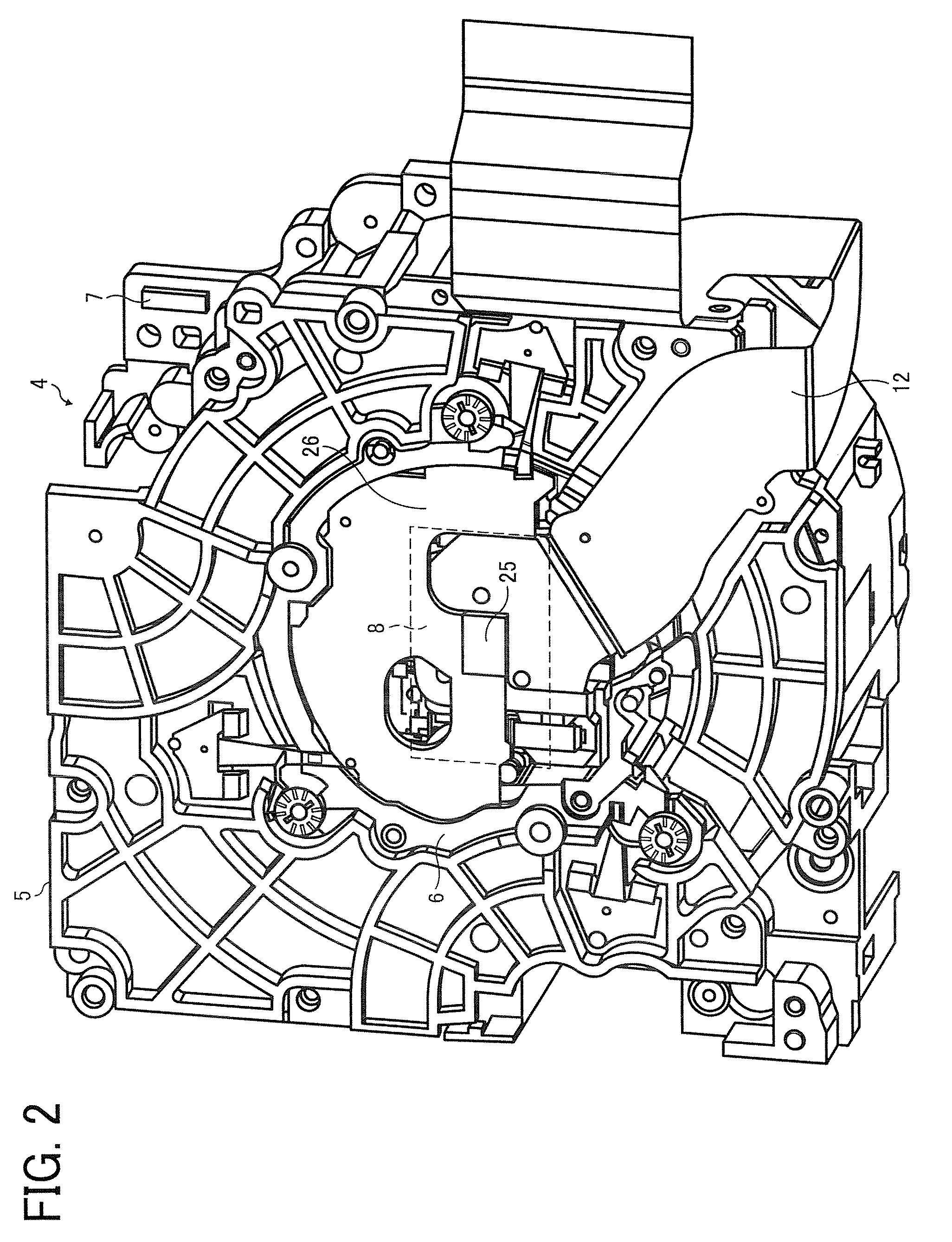
[0079]A digital camera according to the third embodiment has a configuration in which, as shown in FIG. 11, a permanent magnet 29 is fixed to a center portion of the rear of the CCD 8 and a magnetic metal plate 30 is arranged opposed to this permanent magnet 29. This magnetic metal plate 30 is fixed to the CCD retaining frame 6 (see FIG. 2), like the coil supporting member 26 shown in FIG. 2. In this way, the biasing part includes the permanent magnet 29 and the magnetic metal plate 30 in the third embodiment.
[0080]However, the digital camera according to the third embodiment does not include the acceleration sensor that senses acceleration working on the digital camera, the electromagnetic coil that generates the magnetic attraction (or the biasing force) between the electromagnetic coil and the magnetic metal plate arranged opposed to the electromagnetic coil, or the power supply controller (see FIG. 8) that controls the passage of electric current to the electromagnetic coil, alt...
PUM
 Abstract
Description
Claims
Application Information
 - R&D
- Intellectual Property
- Life Sciences
- Materials
- Tech Scout
- Unparalleled Data Quality
- Higher Quality Content
- 60% Fewer Hallucinations
Browse by: Latest US Patents, China's latest patents, Technical Efficacy Thesaurus, Application Domain, Technology Topic, Popular Technical Reports.
© 2025 PatSnap. All rights reserved.Legal|Privacy policy|Modern Slavery Act Transparency Statement|Sitemap|About US| Contact US: help@patsnap.com