Pressure adjusting valve for vehicle fuel line

a technology for adjusting valves and fuel lines, which is applied in the direction of diaphragm valves, fluid pressure control, instruments, etc., can solve the problem of not being able to fine-tune the fuel pressur

Inactive Publication Date: 2009-06-18
HYUNDAI MOTOR CO LTD
View PDF19 Cites 6 Cited by
  • Summary
  • Abstract
  • Description
  • Claims
  • Application Information

AI Technical Summary

Problems solved by technology

This valve can only be open or closed, and thus is not capable of fine-tuning the fuel pressure.

Method used


Image

  • Pressure adjusting valve for vehicle fuel line
  • Pressure adjusting valve for vehicle fuel line
  • Pressure adjusting valve for vehicle fuel line

Examples


Embodiment Construction

[0017]An exemplary embodiment of the present invention will hereinafter be described in detail with reference to the accompanying drawings.

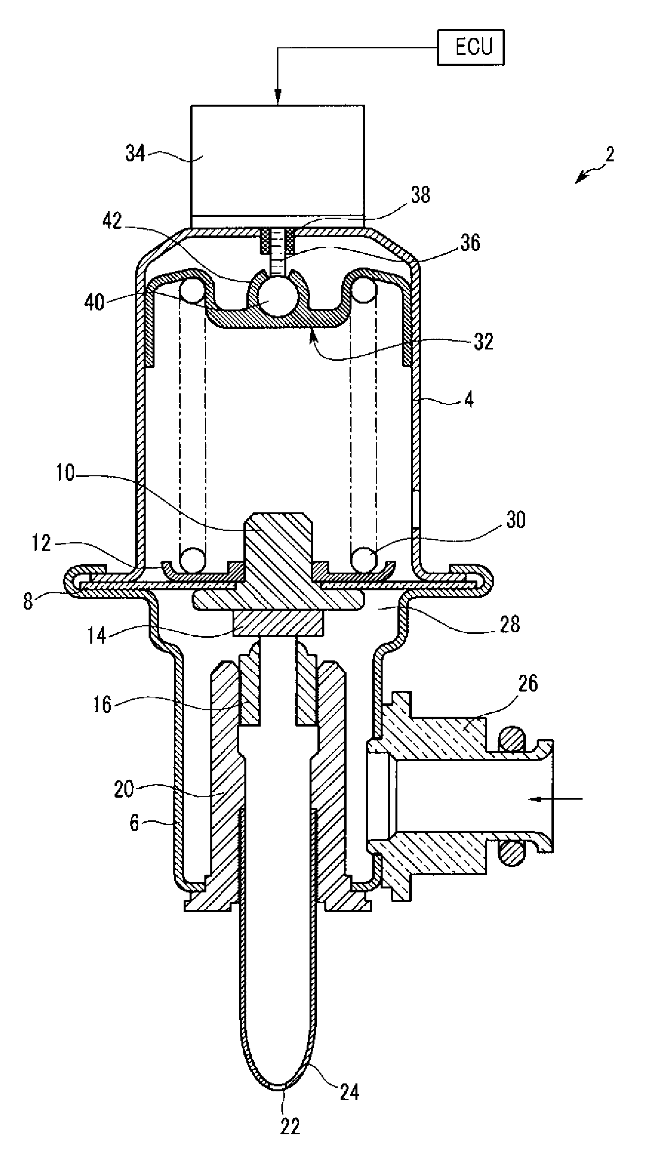
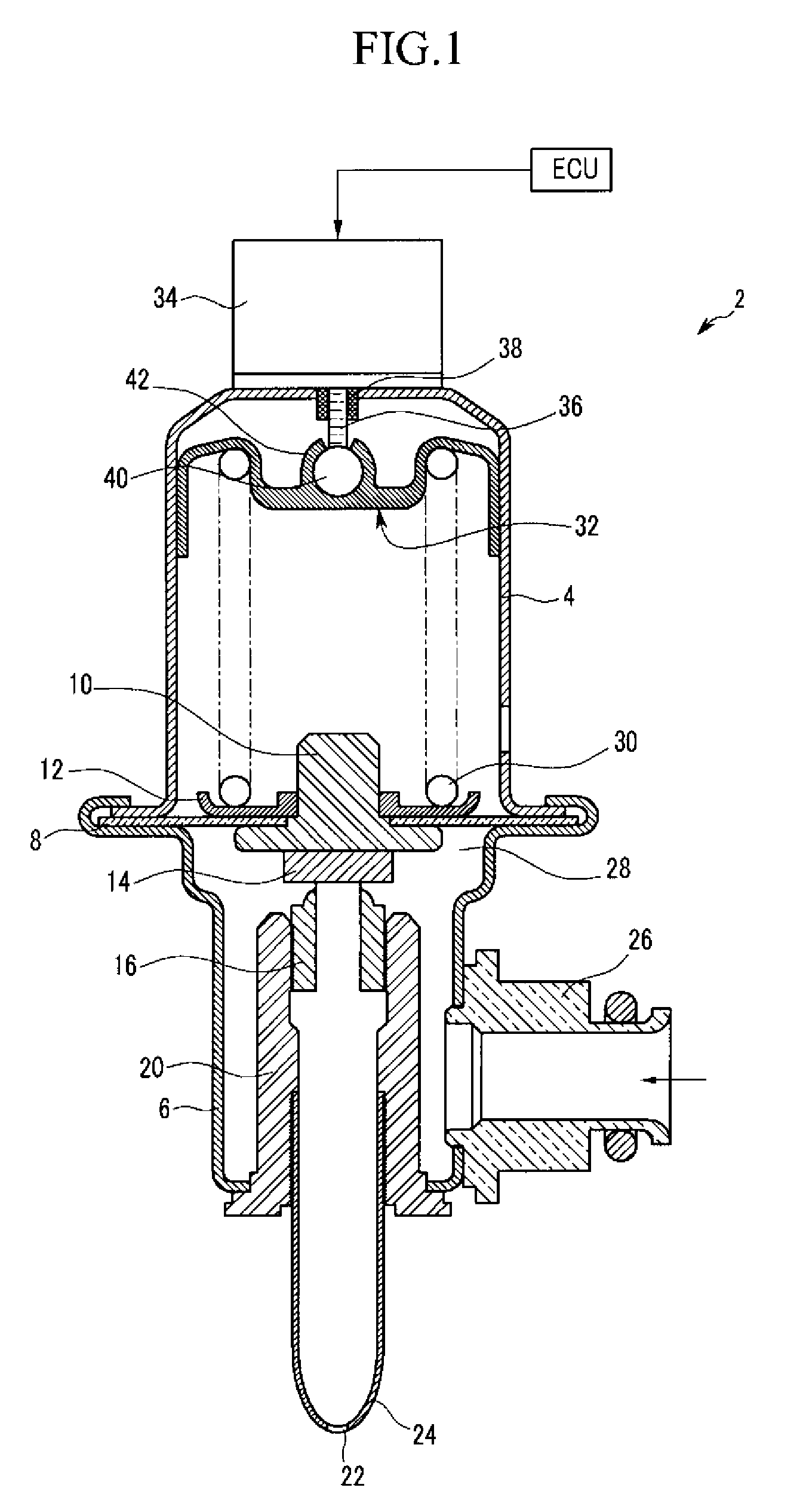
[0018]Referring to FIG. 1, a pressure adjusting valve 2 for a vehicle fuel line (not shown) includes a cylindrical upper housing 4 and a cylindrical lower housing 6. A diaphragm 8 is inserted between the upper housing 4 and the lower housing 6, and an inner body 10 is disposed in the diaphragm 8. A spring seat 12 is disposed on the diaphragm 8. A valve plate 14 is attached to the bottom of the inner body 10, and the valve plate 14 opens and closes a valve body 16 disposed within a bush 20. A fuel nipple 24 with an outlet 22 is disposed below the bush 20. A fuel inlet 26 is provided at a side of the lower housing 6. Fuel is supplied to a hydraulic chamber 28 below the diaphragm 8 through the fuel inlet 26.

[0019]Fuel pressure inside the hydraulic chamber 28 pushes the diaphragm 8. If the pressure inside of the hydraulic chamber 28 overcomes the ela...


PUM


Abstract

A pressure adjusting valve for a vehicle fuel line includes a diaphragm disposed in a housing and dividing the interior of the housing into first and second compartments. A valve plate is provided in the second compartment and attached to the diaphragm. A return unit is provided in the second compartment. An elastic member provides an elastic force to the diaphragm toward the second compartment. An elastic force adjusting unit controls the elastic force of the elastic member.

Description

CROSS-REFERENCE TO RELATED APPLICATION[0001]This application claims priority to, and the benefit of, Korean Patent Application No. 10-2007-0131636, filed in the Korean Intellectual Property Office on Dec. 14, 2007, the entire contents of which are incorporated herein by reference.BACKGROUND OF THE INVENTION[0002](a) Field of the Invention[0003]The present invention relates to a pressure adjusting valve for a vehicle fuel line.[0004](b) Description of the Related Art[0005]A typical pressure adjusting valve includes a spring-biased diaphragm in a fuel hydraulic chamber. If pressure in the fuel hydraulic chamber overcomes the elastic force of the spring, the diaphragm is pushed open, such that the fuel is free to leave the valve through a fuel outlet hole.[0006]This valve can only be open or closed, and thus is not capable of fine-tuning the fuel pressure.[0007]The above information disclosed in this Background section is only for enhancement of understanding of the background of the i...

Claims


Application Information

Patent Timeline
Patent Type & Authority Applications(United States)
IPC IPC(8): F16K7/00F16K31/04
CPCF02M69/54G05D16/0655G05D16/2086G05D16/024F02M37/00F02M69/00F16K7/17
Inventor BONG, HA DONGKIM, JIN YONGHWANG, SEUNGHWANHWANG, IL JOONGSHIN, TAE YEOLCHOI, KWANGSOONLEE, SANGMIN
Owner HYUNDAI MOTOR CO LTD
Why Eureka
Try Eureka