Eureka AIR delivers breakthrough ideas for toughest innovation challenges, trusted by R&D personnel around the world.

Plateless Railway Brake Shoe

a brake shoe and plateless technology, applied in the direction of brake shoe arrangement with braking member, friction lining, transportation and packaging, etc., can solve the problems of steel plate breaking near the key bridge area, vibration of the brake shoe,

Inactive Publication Date: 2009-06-04
RFPC HLDG CORP
View PDF36 Cites 4 Cited by
  • Summary
  • Abstract
  • Description
  • Claims
  • Application Information

AI Technical Summary

Benefits of technology

[0009]Briefly, according to one embodiment of this invention, there is provided a brake shoe formed of friction material for use without a metal backing plate. The brake shoe is defined by a friction surface for bearing upon a wheel tread and an opposed back surface for being placed in contact with and secured to a brake head. The brake shoe has a reinforcing mesh defining a plurality of interstices positioned along the back surface of the brake shoe embedded in a molded friction material. The brake shoe is reinforced with a plurality of metal or non-metal fibers, some of which may extend through the interstices in the wire mesh. The reinforcing fibers may be discrete fibers or fibers in a mesh form or a combination of discrete and mesh form fibers. There is a keyway at least partially formed of the molded fiber reinforced friction material extending away from the back surface of the brake shoe having a keyhole therein such that the portion of the keyway behind the keyhole defines a bridge. The keyway is capable of extending through an opening provided in a brake head when the brake shoe is emplaced on the brake head.
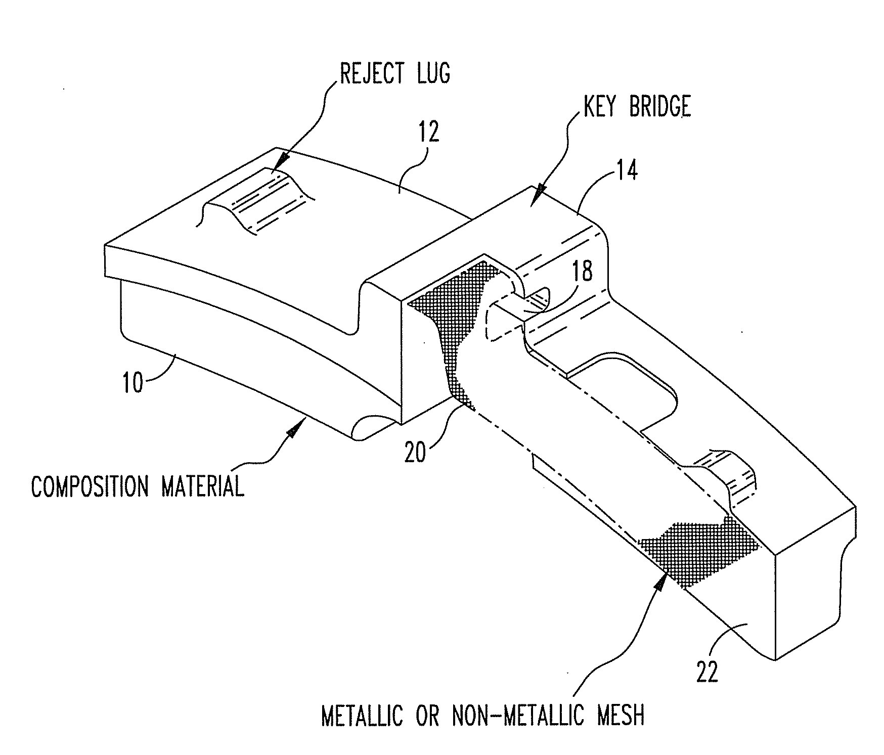
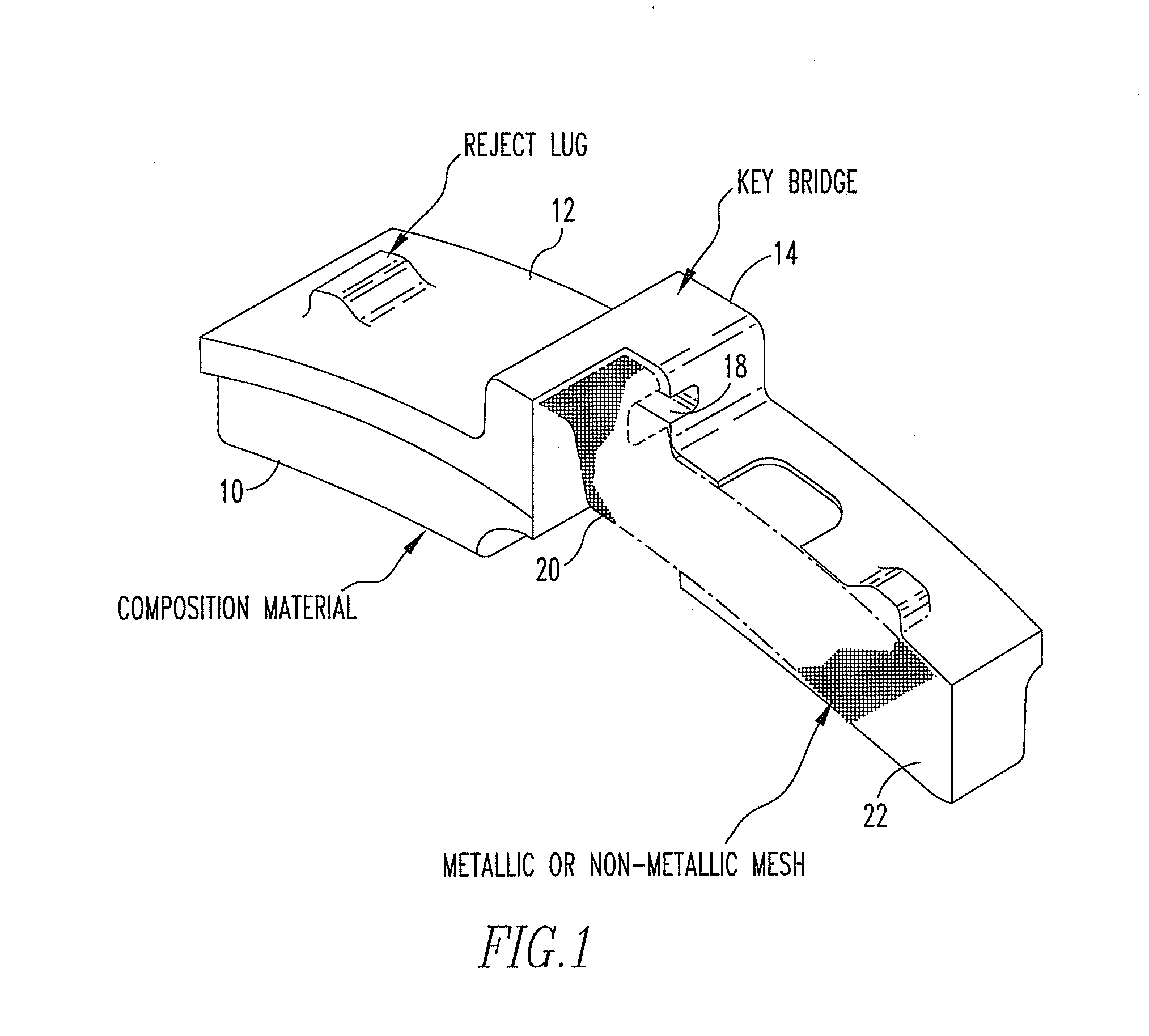
[0010]According to one embodiment, the reinforcing mesh extends along the back surface of the brake shoe and continues through the key bridge of the keyway.
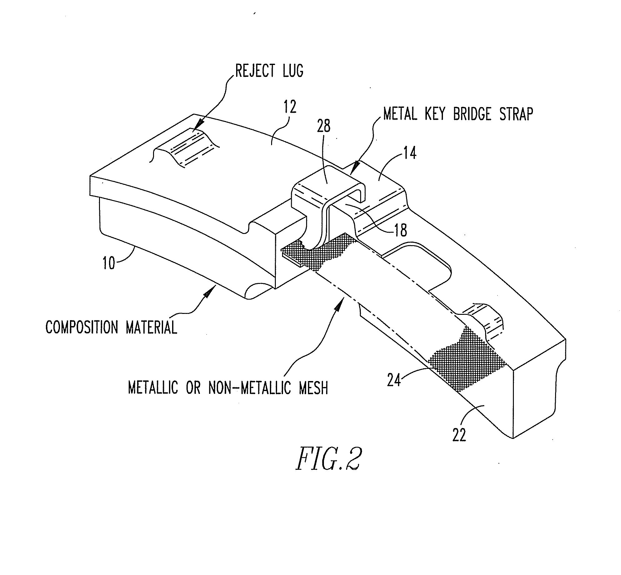
[0011]According to another embodiment, the reinforcing mesh extends along the back surface of the brake shoe and there is a key bridge strap partially encapsulated in the brake shoe.

Problems solved by technology

In addition, when a shoe key becomes loose, the brake shoe is subject to vibration while the rail car is moving.
The key bridge of the steel backing plate impacts the inside of the brake head repeatedly causing the steel plate to break near the key bridge area.

Method used


Image

  • Plateless Railway Brake Shoe
  • Plateless Railway Brake Shoe
  • Plateless Railway Brake Shoe

Examples


Embodiment Construction

[0015]Referring now to FIG. 1, a brake shoe has a friction surface 10 and an opposed back surface 12. A key bridge 14 is positioned on the back side of brake shoe. A keyhole 18 is formed in the key bridge. A reinforcing mesh 20 is positioned along the back surface of the brake shoe embedded therein. The brake shoe is formed of a molded composite containing a plurality of reinforcing fibers 22. The compound and the reinforcing fibers extend within the interstices of the reinforcing mesh.

[0016]Referring now to FIG. 2, a brake shoe has a friction surface 10 and an opposed back surface 12. A key bridge 14 is positioned on the back side of brake shoe. A reinforcing mesh 24 is positioned along the back surface of the brake shoe embedded therein. The brake shoe is formed of a molded composite 22 containing a plurality of reinforcing fibers. The compound 22 and the reinforcing fibers extend within the interstices of the reinforcing mesh. A metal key bridge strap 28 is partially encapsulated...


PUM


Abstract

A brake shoe formed of friction material for use without a metal backing plate. The brake shoe is defined by a friction surface for bearing upon a wheel tread and an opposed back surface for being placed in contact with and secured to a brake head. The brake shoe has a reinforcing mesh defining a plurality of interstices positioned along the back surface of the brake shoe embedded in a molded friction material that is reinforced with a plurality of fibers. A keyway is at least partially formed of the molded fiber reinforced friction material extending away from the back surface of the brake shoe.

Description

BACKGROUND OF THE INVENTION[0001]1. Field of the Invention[0002]This invention relates to railway brake shoes that do not require the traditional back plate.[0003]2. Description of Related Art[0004]Rail cars are supported and guided by steel wheels. The treads at the outer circumference of the wheels ride over steel rails. Rail car brakes comprise brake shoes that are brought into frictional engagement with the wheel treads. The brake shoes are supported by brake heads which, in tarn, are movably supported by the brake rigging comprised of a system of levers and a pneumatic cylinder. Brake shoes are comprised of various materials that are selected for their frictional characteristics and for the effect on the wear life of the wheel treads. Many brake shoes are composites of materials having different characteristics. In a typical composite brake shoe, materials of differing frictional characteristics bear upon the wheel tread during braking[0005]Standard railway brake shoes in North...

Claims


Application Information

Patent Timeline
Patent Type & Authority Applications(United States)
IPC IPC(8): F16D69/00
CPCB61H1/00F16D2200/006F16D65/062
Inventor BOWDEN, A. GARYRUMPH, TIMOTHY A.
Owner RFPC HLDG CORP
Why Eureka
Eureka Blog
Learn More