
Pneumatic tool for use in cold environments

a pneumatic tool and cold environment technology, applied in the field of power tools, can solve the problems of patents tools that do not disclose pressured air supply hoses,

Inactive Publication Date: 2009-05-28
MULUSHOFF NIKOLAI
View PDF3 Cites 2 Cited by
  • Summary
  • Abstract
  • Description
  • Claims
  • Application Information

AI Technical Summary

Problems solved by technology

pneumatic tools are known; however, such tools do not disclose a pressured air supply hose having an electrical heating wire imbedded in the wall of the hose.
This patent does not disclose a pressured air supply hose having an electrical heating wire imbedded in the wall of the hose.
The apparatus includes a nailing gun, however, the gun does not disclose a pressured air supply hose having an electrical heating wire imbedded in the wall of the hose.
The apparatus includes a nailing gun, however, the gun does not include does not disclose a pressured air supply hose having an electrical heating wire imbedded in the wall of the hose.
The apparatus includes a nailing gun, however, the gun does not disclose a pressured air supply hose having an electrical heating wire imbedded in the wall of the hose.
However, this does not teach the nailing gun with a pressured air supply hose having an electrical heating wire imbedded in the wall of the hose.

Method used


Image

  • Pneumatic tool for use in cold environments
  • Pneumatic tool for use in cold environments

Examples


Embodiment Construction

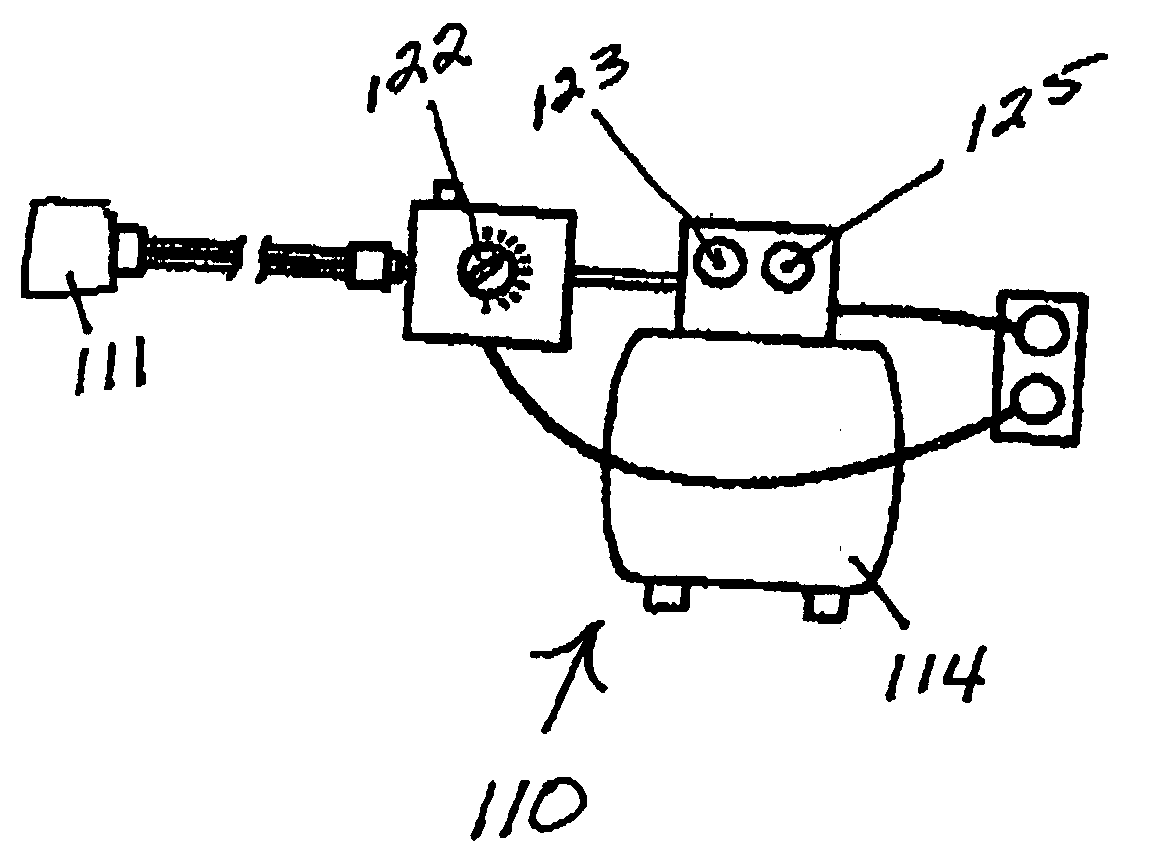
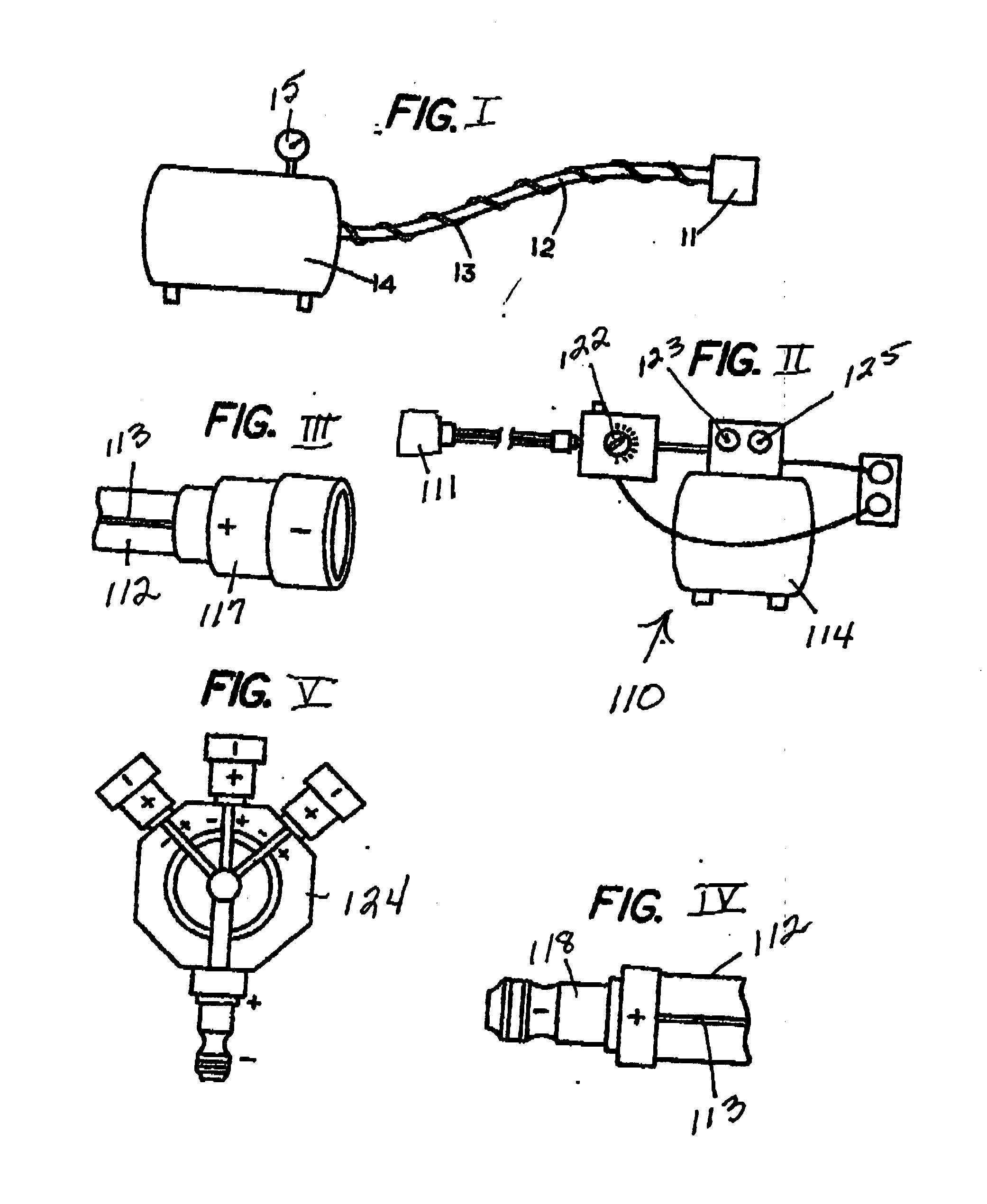
[0018]A pneumatic tool system 10 (FIG. I) for use in extreme cold without the risk of freezing of the tube mechanism 12 providing the pressurized air. The tool system 10 has a pneumatic tool 11, such as a nailer, a saw, a drill or a similar conventional gas driven tool. Tubular mechanism 12 connected to feed pressurized gas to said tool 11. Pressure source of gas, such as a conventional compressor or compressed gas tank 14. The pneumatic tool system 10 of wherein said tubular mechanism for applying heat electrical heating coil 13, comprises tubing 12 said electrical heating coil means embedded in the walls of said tubing. The tubing 12 may have a plurality of discrete sections of tubing to permit elongation of the tubing. The plurality of discrete sections of tubing has connectors disposed between said sections of the hoses provides electrical connection. The compressed gas tank 14 may have a gauge 15 to show how much gas remains in the tank 14. The compressed gas may be compressed ...


PUM


Abstract

Disclosed is a pneumatic tool for use in extreme cold without the risk of freezing of the pressure providing the air: air tubing has electrical heating coils embedded in the walls of the tubing, the connectors between the sections of the hoses.

Description

FIELD OF THE INVENTION[0001]The invention in the field of power tools, such as pneumatic nailers, saws, and drills.BACKGROUND OF THE INVENTION[0002]pneumatic tools are known; however, such tools do not disclose a pressured air supply hose having an electrical heating wire imbedded in the wall of the hose.[0003]U.S. Pat. No. 4,197,974 (MORTON et. al.) Shows a conventional NAILER. This patent does not disclose a pressured air supply hose having an electrical heating wire imbedded in the wall of the hose.[0004]U.S. Pat. No. 4,834,131 (AUSTIN) Shows a SAFETY SYSTEM FOR PNEUMATIC TOOLS. The safety system provides an escape valve for relieving excessive air pressure. This patent does not disclose a pressured air supply hose having an electrical heating wire imbedded in the wall of the hose.[0005]U.S. Pat. No. 5,040,563 (WOOD) Shows an ADJUSTABLE AIR PRESSURE VALVE. This patent does not disclose a pressured air supply hose having an electrical heating wire imbedded in the wall of the hose....

Claims


Application Information

Patent Timeline
IPC IPC(8): B25C1/04H05B3/58
CPCH05B3/58B25C1/04
Inventor MULUSHOFF, NIKOLAI
Owner MULUSHOFF NIKOLAI
Learn More