
Malleable Prosthesis with Enhanced Concealability

a penile prosthesis and malleable technology, applied in the field of malleable penile prostheses, can solve problems such as difficulty in concealing devices

Active Publication Date: 2009-04-23
BOSTON SCI SCIMED INC
View PDF103 Cites 7 Cited by
  • Summary
  • Abstract
  • Description
  • Claims
  • Application Information

AI Technical Summary

Problems solved by technology

One of the problems involved in malleable penile implants is the difficulty in concealing the device by positioning the rods in a bent configuration and remaining in that concealed position.
This difficulty is often due to the large diameter of the rod.

Method used


Image

  • Malleable Prosthesis with Enhanced Concealability
  • Malleable Prosthesis with Enhanced Concealability
  • Malleable Prosthesis with Enhanced Concealability

Examples


Embodiment Construction

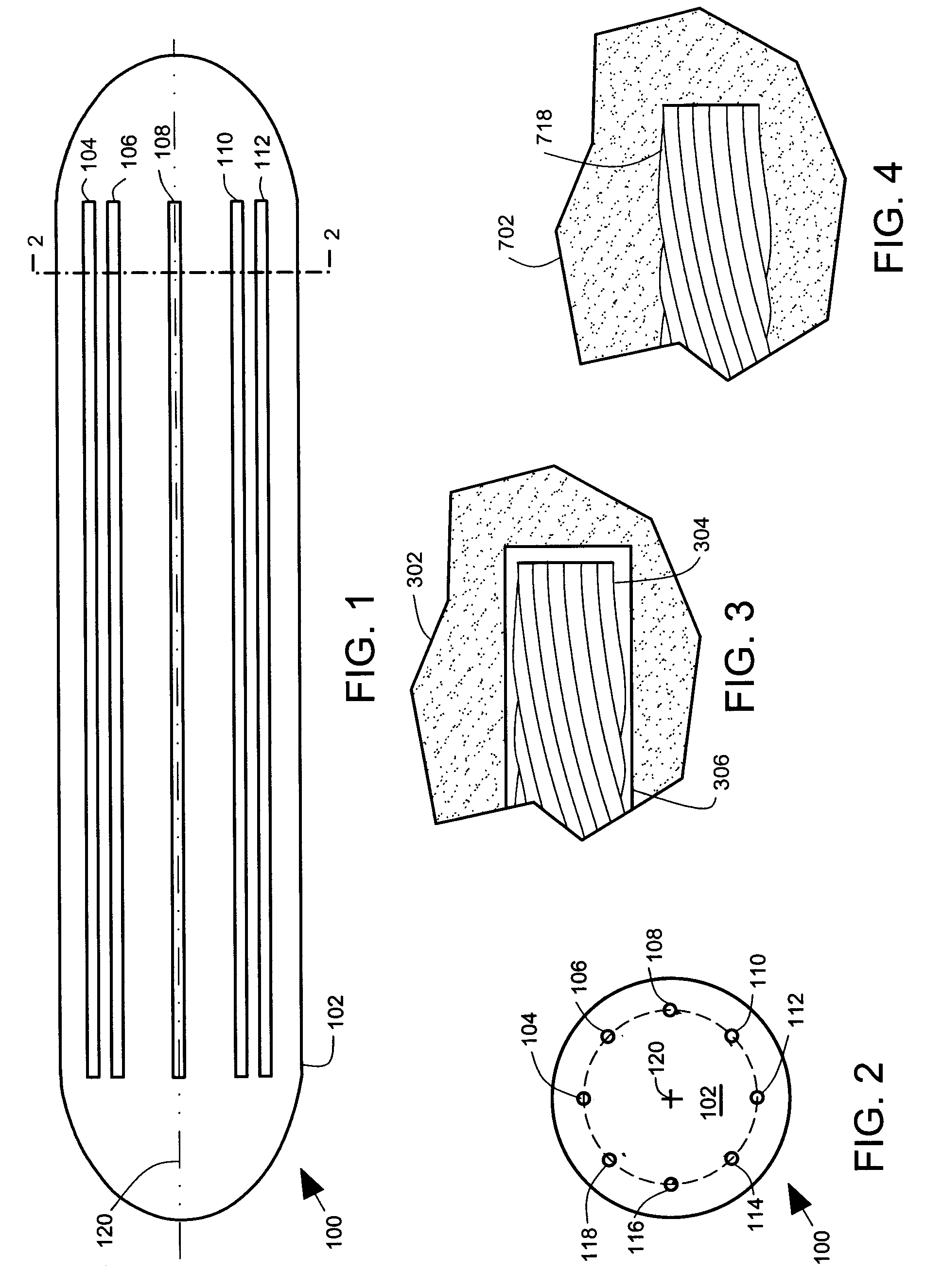
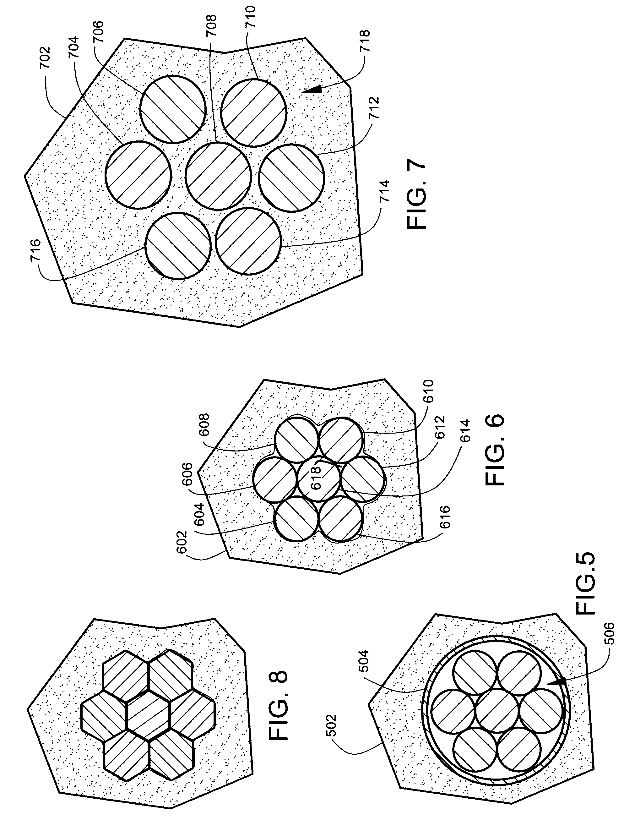
[0009]FIG. 1 illustrates a prosthetic device 100, and FIG. 2 illustrates a cross-sectional view (along line 2-2 in FIG. 1) of the prosthetic device 100. The prosthetic device 100 comprises a column 102 formed of resilient material. The resilient material can comprise silicone or other known biocompatible resilient prosthesis material. The prosthetic device 100 comprises multiple malleable cores 104, 106, 108, 110, 112, 114, 116118 arranged inside the column 102. The multiple malleable cores 104, 106, 108, 110, 112, 114, 116, 118 are spaced apart from one another, spaced apart from a central axis 120, and positioned adjacent an outer diameter of the column 102. In one embodiment, the multiple malleable cores 104, 106, 108, 110, 112, 114, 116, 118 are positioned in a circular pattern at equally spaced intervals as illustrated. In the embodiment shown in FIGS. 1-2, eight malleable cores are illustrated, however, other numbers of cores in a range of 3 to 9 cores are also contemplated. E...


PUM


Abstract

A penile prosthetic device comprising a column formed of resilient material. The prosthetic device comprises multiple malleable cores arranged inside the column. The multiple malleable cores are spaced apart from one another.

Description

CLAIM TO PRIORITY[0001]The present application claims priority to U.S. provisional patent application No. 60 / 981,844, filed Oct. 23, 2007, and entitled “Malleable Prosthesis with Multiple Malleable Cores Not On Center.” The identified provisional patent application is hereby incorporated by reference in its entirety.FIELD OF THE INVENTION[0002]The invention relates to implantable prosthetic devices. In particular, but not by way of limitation, the invention relates to implantable malleable (non-inflatable) penile prostheses.BACKGROUND OF THE INVENTION[0003]There are many causes of male impotence including those that are psychologically based as well as trauma related impotence. Procedures have been developed for treating impotence, and one such procedure involves the implantation of a penile prosthesis. There are two general types of penile implants, namely, the inflatable penile implant and the noninflatable penile implant. The noninflatable implants include those which incorporate...

Claims


Application Information

Patent Timeline
IPC IPC(8): A61F2/02A61F5/00
CPCA61F2/26A61F2005/411A61F5/41A61F2230/0006A61F2230/0069A61F2250/0006A61F2250/0018A61F2250/0029A61F2250/0032A61H19/44
Inventor GEORGE, STEPHANIE A.NELSON, SARA ELIZABETHROWLAND, RANDALL P.KUYAVA, CHARLES C.
Owner BOSTON SCI SCIMED INC
Learn More