Non-snag polymer ligating clip

a polymer and ligating clip technology, applied in the field of surgical clips, can solve the problems of limited space and visibility, time-consuming and difficult to perform complex manipulations of surgical threads for ligation, and requiring complex needle manipulations, etc., to achieve sufficient strength, minimize interference, and high degree of security

Inactive Publication Date: 2009-04-02
KENNEDY DANIEL L +2
View PDF25 Cites 182 Cited by
  • Summary
  • Abstract
  • Description
  • Claims
  • Application Information

AI Technical Summary

Benefits of technology

[0011]In accordance with the present disclosure, a polymeric surgical clip is provided of the type comprising first and second legs joined at their proximal ends by a flexible hinge section. Each leg has a vessel clamping inner surface, an opposite outer surface, and a pair of opposing side surfaces. The vessel clamping inner surface is in opposition to the vessel clamping inner surface of the other leg. Further, a female locking member is positioned on the distal end of the first leg and a male locking member is positioned on the distal end of the second leg. The female and male locking members are formed such that when the first and second leg members are moved from an open position to a closed position about the hinge section, the male locking member is lockingly engaged in the female locking member so as to removably lock the clip in the closed position.
[0012]Example embodiments of the invention include a polymeric non-snag surgical clip having: a first leg and a second leg, each of said legs having an inner vessel-clamping surface, an outer surface and a pair of opposing side surfaces flanking said inner and outer surfaces; a hinge section integrally disposed between and joining proximal ends of said first and second legs; a female locking member positioned on the distal end of said first leg and a male locking member positioned on the distal end of said second leg; and at least one first recess substantially submerged within one of the pair of opposing side surfaces of said first leg, and at least one second recess substantially submerged within one of the pair of opposing side surfaces of said second leg, said at least one first and second recesses serving to allow for engagement and application of the surgical clip by a clip applier apparatus.
[0013]In other embodiments, the polymeric non-snag surgical clip may include: a first leg and a second leg, each of said legs having an inner vessel-clamping surface, an outer surface and a pair of opposing side surfaces flanking said inner and outer surfaces; a hinge section integrally disposed between and joining proximal ends of said first and second legs; a female locking member positioned on the distal end of said first leg and a male locking member positioned on the distal end of said second leg; and a first recess substantially submerged within the outer surface of said first leg, and a second recess substantially submerged within the outer surface of said second leg, said first and second recesses serving to allow for engagement and application of the surgical clip by a clip applier apparatus.

Problems solved by technology

The use of surgical thread for ligation requires complex manipulations of the needle and suture material to form the knots required to secure the vessel.
Such complex manipulations are time-consuming and difficult to perform, particularly in endoscopic surgical procedures, which are characterized by limited space and visibility.
With the advent of high technology diagnostic techniques using computer tomography (CATSCAN or CT) and magnetic resonance imaging (MRI), metallic clips have been found to interfere with the imaging techniques.
Unlike metallic clips, which are usually symmetric, polymeric clips are usually asymmetric in design and hence lack an axis of symmetry.
However, metal clips are not viable when there is a desire to use a CT scan to study the patency of a graft after bypass surgery.
Thus, there is a long-felt need in coronary artery bypass surgery to find an alternative to the metal ligating clip used to tie off branches of the IMA being used for a coronary artery bypass graft since the metal ligating clips do not readily lend themselves to CT scans to study the patency of a graft after a bypass.

Method used


Image

  • Non-snag polymer ligating clip
  • Non-snag polymer ligating clip
  • Non-snag polymer ligating clip

Examples


Embodiment Construction

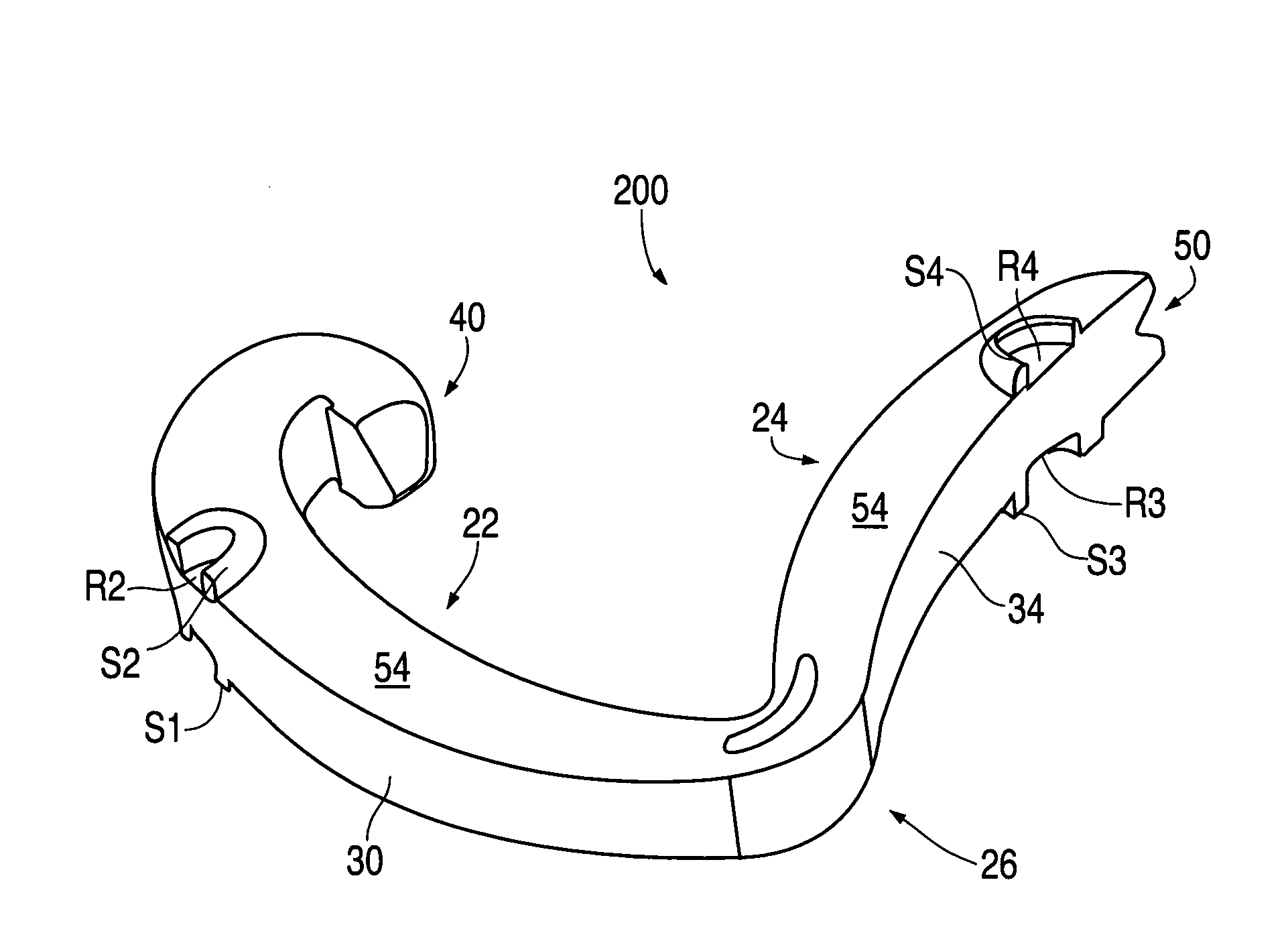
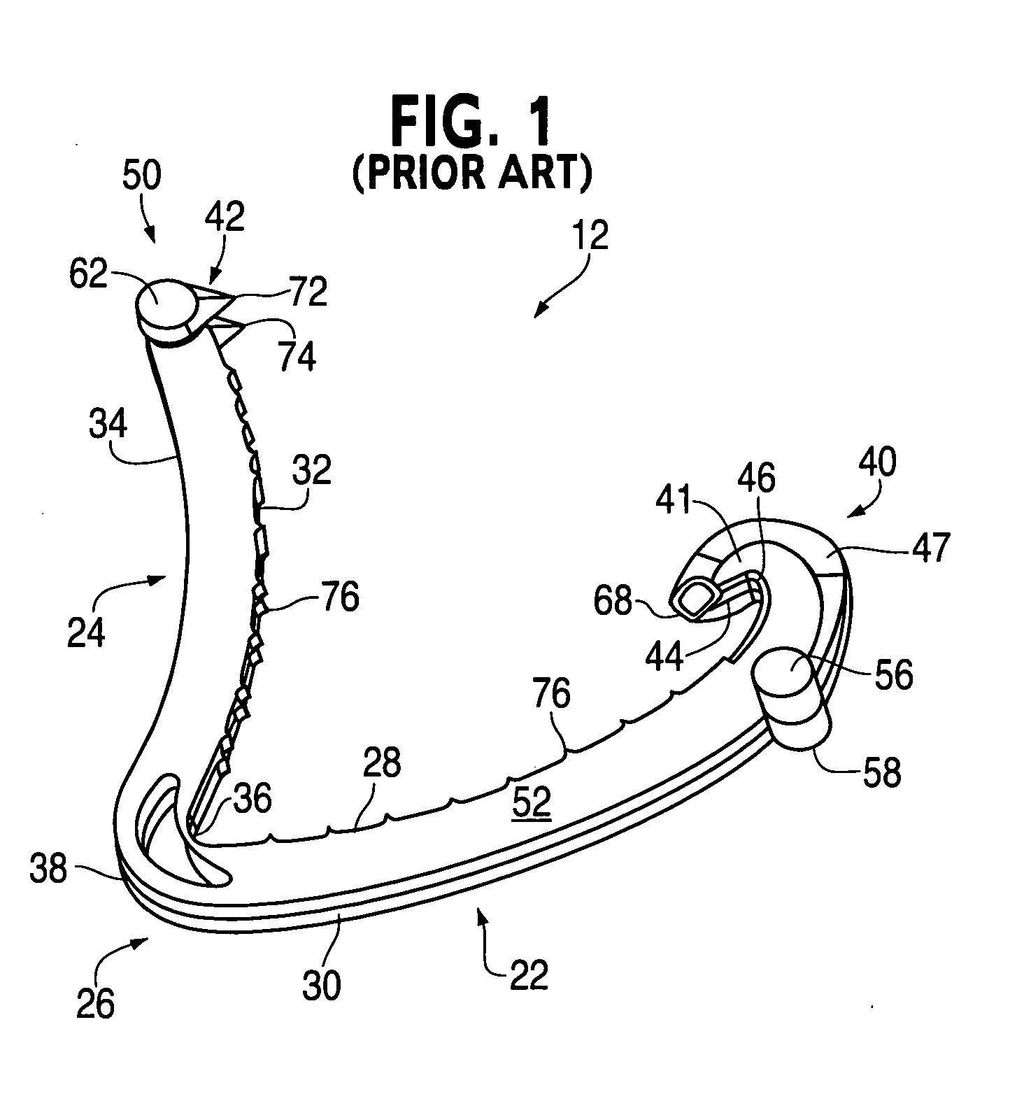
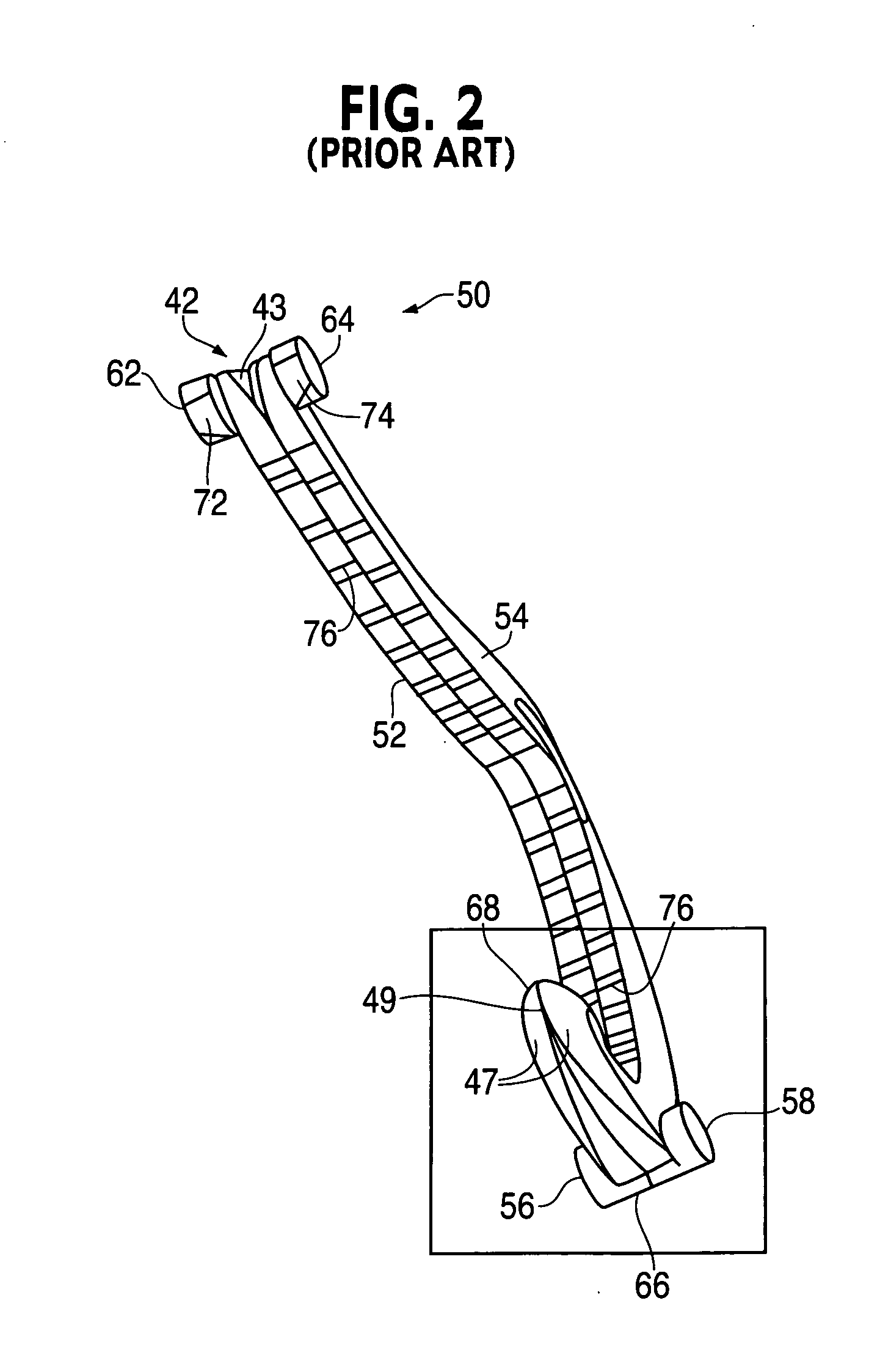
[0034]Referring first to FIGS. 1-2 of the drawings, one example is illustrated of a conventional asymmetric surgical clip 12. Clip 12 and others of similar design are particularly useful as hemostatic clips that can be latched around a vessel or other type of tissue to ligate the vessel and thereby stop or reduce the flow of fluid through the vessel. Clip 12 can be constructed from any suitable biocompatible material. However, the presently disclosed subject matter is particularly suitable for practice with polymeric clips. Thus, clip 12 preferably comprises a one-piece integral polymeric body formed from a suitable strong biocompatible engineering plastic such as the type commonly used for surgical implants. Examples include, but are not limited to, acetyl polyoxymethylene (POM), polyethylene terephthalate (PET), polybutylene terephthalate (PBT), polyoxymethylene, or other thermoplastic materials having similar properties that can be injection-molded, extruded or otherwise processe...


PUM


Abstract

A polymeric, surgical clip having first and second curved legs with each having a pair of opposing side surfaces joined at their proximal ends by a flexible hinge section and movable from an open position to a closed position for clamping a vessel between curved opposing inner surfaces. The first leg terminates at its distal end in a female locking member, and the second leg member terminates in a male locking member complimentary to the female locking member. The clip is provided with low profile boss-like elements on the legs thereof to reduce the risk of snagging a suture during coronary artery bypass graft surgery.

Description

PRIORITY[0001]This application is a continuation of U.S. patent application Ser. No. 11 / 283,848 filed Nov. 22, 2005, the entire contents of which are incorporated by reference herein.TECHNICAL FIELD[0002]The present invention relates to surgical clips, and more particularly to a non-snag polymer ligating clip which is easier to introduce into tight spaces during coronary artery bypass graft surgery and which is less prone to catch a suture when attaching a graft IMA (internal mammary artery) to the coronary artery during the coronary artery bypass graft procedure. More particularly, the present disclosure relates to an improved surgical ligating clip that can be used in coronary artery bypass graft surgical procedures without catching a suture during attachment of a graft IMA to the coronary artery and which subsequently allows for CT (computer tomography) to check patency in the coronary artery bypass graft juncture since the clip is translucent and not visible on CT.BACKGROUND ART...

Claims


Application Information

Patent Timeline
Patent Type & Authority Applications(United States)
IPC IPC(8): A61B17/122
CPCA61B17/1227A61B17/122
Inventor KENNEDY, DANIEL L.WILSON, JR., DONALD F.KNODEL, BRYAN D.
Owner KENNEDY DANIEL L
Why Eureka
Try Eureka