Systems and Methods for Neuro-EEG Synchronization Therapy
- Summary
- Abstract
- Description
- Claims
- Application Information
AI Technical Summary
Benefits of technology
Problems solved by technology
Method used
Image
Examples
example 1
[0305]In some embodiments, described are devices that provide low frequency near-sinusoidal TMS therapy by rotating at least one permanent magnet in close proximity to the subject's head. The direction of rotation relative to the subject can vary depending on the specific therapy desired. Also, the speed of rotation can be adjusted to provide the optimal therapeutic benefit. The speed adjustment itself can come from the user of the device or from a controller that uses feedback from a bio-sensor to determine the optimal speed.
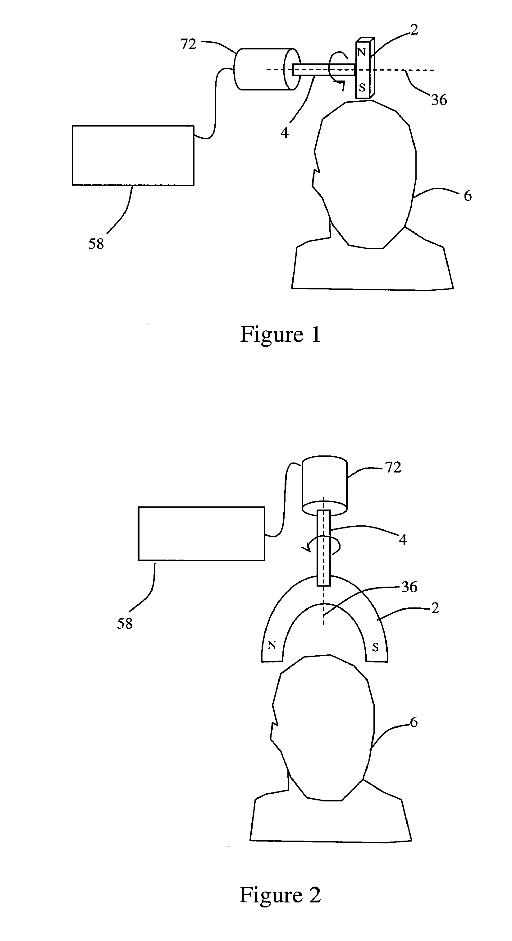
[0306]In particular embodiments, a bar magnet can be mounted at the end of the shaft with the line through the poles perpendicular to the axis of the shaft. The shaft can be rotated by an adjustable motor. The magnet can rotate so that the plane of rotation is perpendicular to the surface of the scalp. Accordingly, the positive and negative poles of the magnet can be alternately brought in close proximity to the scalp. This can create a near-sinusoidal magnetic...
example 2
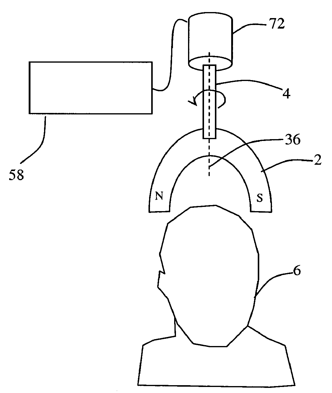
[0307]In particular embodiments, a horseshoe magnet can be mounted at the end of the shaft with the poles positioned at the far end from the shaft. The shaft can be rotated by an adjustable motor, as in the previous example. The magnet can be positioned above the subject's scalp such that the plane of rotation is parallel to the surface of the scalp. Accordingly, the positive and negative poles can rotate in a circle around the scalp. This can create a sinusoidal magnetic field in the brain in which the phase of the magnetic field is dependent on where the magnetic poles are in their rotation. In general, the magnetic field under one pole will be of opposite polarity to the magnetic field under the opposite pole.
example 3
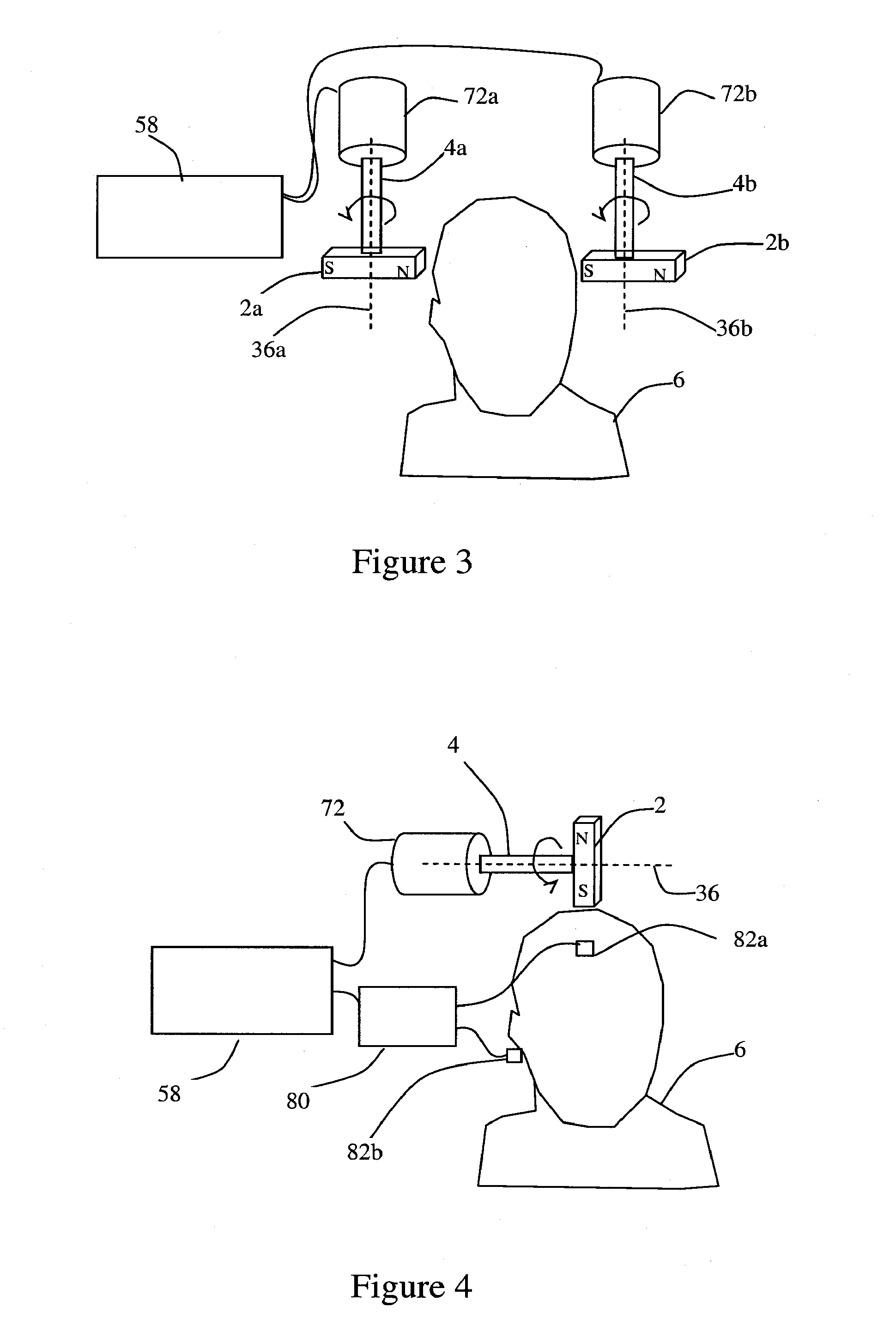
[0308]In particular embodiments, two bar magnets can be used, each mounted at the end of a shaft. The shafts can be rotated by adjustable motors. The magnets can be positioned on opposite sides of the subject's head, and they are rotated synchronously to provide a more uniform phase for the magnetic field in the brain. When the north Pole of one bar magnet is next to the subject's scalp, the south Pole of the other magnet will be next to the subject's scalp on the opposite side of the subject's head.
PUM
 Abstract
Description
Claims
Application Information
 - R&D
- Intellectual Property
- Life Sciences
- Materials
- Tech Scout
- Unparalleled Data Quality
- Higher Quality Content
- 60% Fewer Hallucinations
Browse by: Latest US Patents, China's latest patents, Technical Efficacy Thesaurus, Application Domain, Technology Topic, Popular Technical Reports.
© 2025 PatSnap. All rights reserved.Legal|Privacy policy|Modern Slavery Act Transparency Statement|Sitemap|About US| Contact US: help@patsnap.com


