
Electronic game controller

a game controller and controller technology, applied in the field of electronic game controllers, can solve the problems of not meeting the input requirements of many existing different kinds of electronic games, the difficulty of meeting the input requirements of many existing electronic games, and the difficulty of game controllers providing only one way of being held, etc., to achieve the effect of making users enjoy the interactive electronic games well

Active Publication Date: 2009-03-26
CM HK LTD
View PDF9 Cites 20 Cited by
  • Summary
  • Abstract
  • Description
  • Claims
  • Application Information

AI Technical Summary

Benefits of technology

[0007]A main object of the present invention is to provide an electronic game controller which can provide users with more than two ways of being held for controlling special indicators on display pictures for the electronic games in an interactive way.
[0009]The efficacy of the present invention is as follows: the front body and the rear body are pivotally connected with each other via the rotating mechanism so that the rear body of the present invention can rotate relative to the front body to form more than two kinds of structures for being held by users, such as a straight stick or a handgun-shaped structure, for adapting for more kinds of interactive electronic games, thereby users can rotate and adjust the rear body to the easiest held position, so the present invention can meet the requirements of human engineering and enhance users' enjoyment of playing electronic games.

Problems solved by technology

However, with a single-handed input device it is difficult to meet the input requirements of the many existing different kinds of electronic games.
In particular, a game controller providing only one way of being held cannot meet the requirements of playing all kinds of electronic games.
However, the game controllers described above only provide one way of being held such as a straight stick or a handgun-shaped structure, and therefore can only be used for a limited choice of interactive electronic games and sometimes cannot even make users enjoy the interactive electronic games well.

Method used


Image

  • Electronic game controller
  • Electronic game controller
  • Electronic game controller

Examples


Embodiment Construction

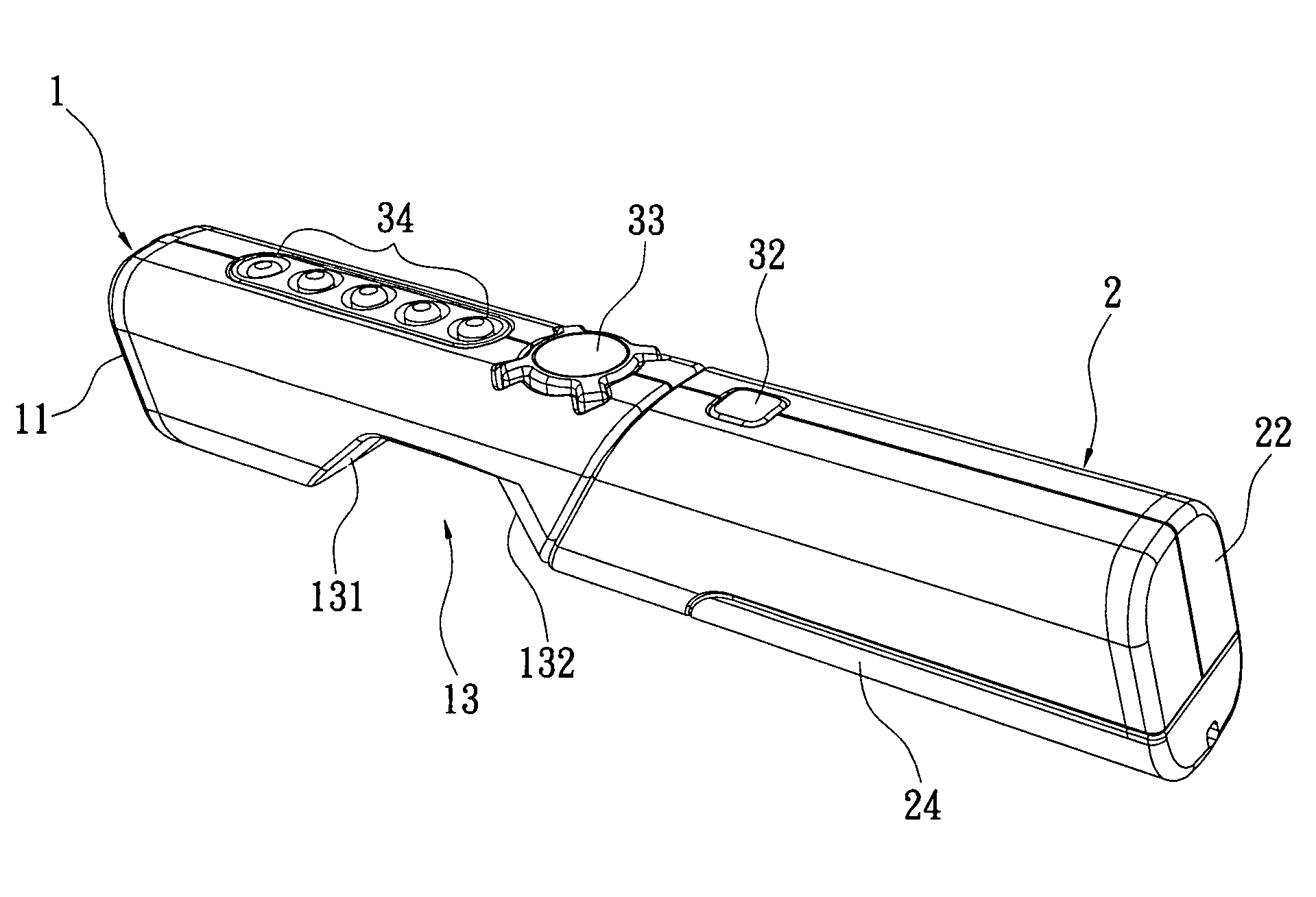
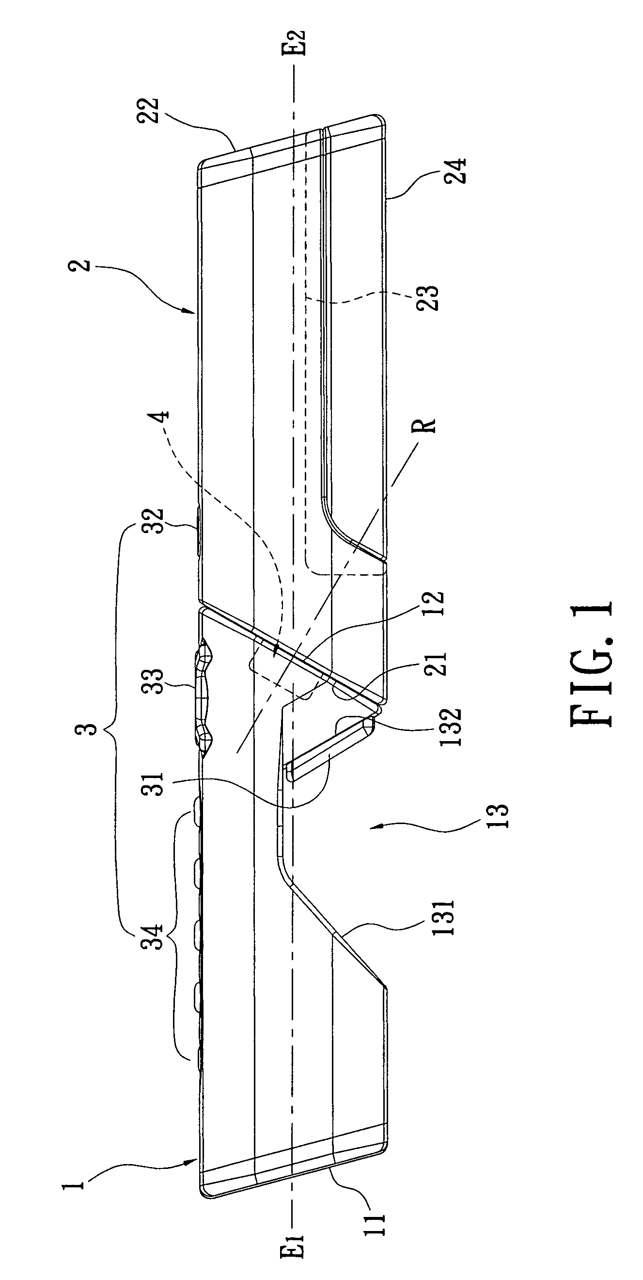
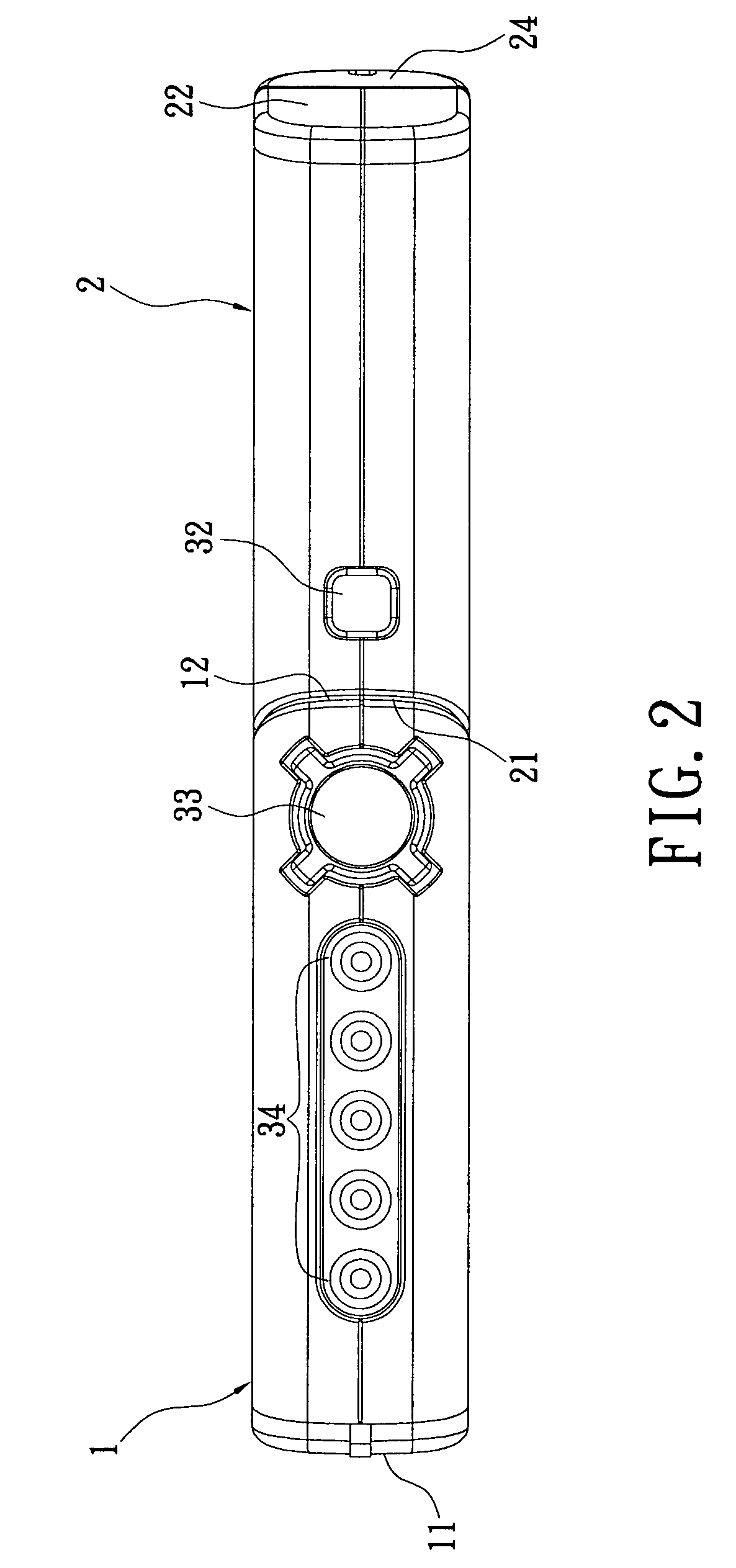
[0018]At first, please refer to FIGS. 1-3 illustrating an embodiment of an electronic game controller of the present invention. The electronic game controller includes a front body 1, a rear body 2, a function key group 3, a rotating mechanism 4 and an orientation sensing input module 5 (as shown in FIG. 7). The front body 1 has a longitudinal axis and two lateral axes and includes a first end surface 11, a second end surface 12 and a receiving portion 13. The first end surface 11 is formed on the front portion of the front body 1, and the second end surface 12 is formed on the rear portion of the front body 1 and is non-orthogonal to the longitudinal axis E1 of the front body 1. In the shown embodiment, the plane of second end surface 12 of the front body 1 forms an angle with the plane of upper surface of the front body 1 of more than 45 degrees but less than 90 degrees. The receiving portion 13 may be a groove, a protruding portion or a lateral through-hole and so on, which is fo...


PUM


Abstract

An electronic game controller includes a front body, a rear body, a plurality of function keys and a rotating mechanism. The front body includes a second end surface non-orthogonal to its longitudinal axis. The rear body includes a third end surface parallel to the second end surface and non-orthogonal to the longitudinal axis of the rear body. The function keys are disposed on the front and the rear bodies. The rotating mechanism is connected with the second and the third end surfaces, that is, the front and the rear bodies are pivotally connected with each other via the rotating mechanism. Accordingly, since the rear body can rotate relative to the front body and be positioned via the rotating mechanism, the present invention can provide more than two ways of being held to enhance users' enjoyment of playing electronic games.

Description

BACKGROUND OF THE INVENTION[0001]1. Field of the Invention[0002]The present invention relates to an electronic game controller, more especially to an electronic game controller which can be held by users for controlling special indicators on display pictures for electronic games.[0003]2. Description of Related Art[0004]A conventional electronic game controller for a game machine is generally held in both hands of a user. The user can press keys on the controller to input signals into the game machine. At present, stick-shaped controllers are designed which can be operated using only one hand.[0005]However, with a single-handed input device it is difficult to meet the input requirements of the many existing different kinds of electronic games. In particular, a game controller providing only one way of being held cannot meet the requirements of playing all kinds of electronic games. For example, for electronic ball games, such as baseball, tennis ball and so on, the game controller sh...

Claims


Application Information

Patent Timeline
Patent Type & Authority Applications(United States)
IPC IPC(8): A63F9/24
CPCA63F2300/1043A63F13/06A63F2300/204A63F13/24A63F13/537A63F13/92A63F2300/303A63F13/20A63F13/213
Inventor YE, ZHOU
Owner CM HK LTD
Learn More