Control method and apparatus for strip-shaped material printing press
a control method and printing press technology, applied in printing, thin material folding, thin material processing, etc., can solve the problems of corresponding increase in waste of paper and heavy burden, and achieve the effect of reducing the burden on the operator, increasing the rate of operation, and constant folding position of the signature transported to the chopper
- Summary
- Abstract
- Description
- Claims
- Application Information
AI Technical Summary
Benefits of technology
Problems solved by technology
Method used
Image


Examples
embodiment 1
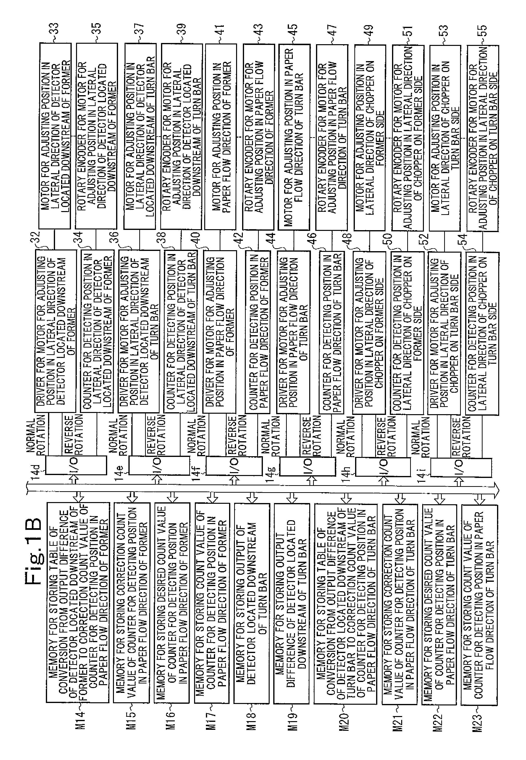
[0078]FIGS. 1A and 1B are block diagrams of a former and turn bar control device showing Embodiment 1 of the present invention. FIGS. 2A to 2D are motion flow charts of the former and turn bar control device. FIGS. 3A to 3D are motion flow charts of the former and turn bar control device. FIGS. 4A and 4B are motion flow charts of the former and turn bar control device. FIGS. 5A and 5B are motion flow charts of the former and turn bar control device. FIG. 11 is a perspective view of a folding machine in a web rotary printing press. FIG. 12 is an explanation drawing of an air blowing device of the former. FIG.13 is an explanation drawing of a moving mechanism of the former. FIG. 14 is an explanation drawing of an air blowing device of the turn bar. FIG. 15 is an explanation drawing of a moving mechanism of the turn bar. FIG. 16 is an explanation drawing of a moving mechanism of the chopper.
[0079]As shown in FIG. 11, a web (strip-shaped material) W, which has been fed to a folding mach...
embodiment 2
[0170]FIGS. 6A and 6B are block diagrams of a chopper control device showing Embodiment 2 of the present invention. FIGS. 7A to 7D are motion flow charts of the chopper control device. FIGS. 8A to 8D are motion flow charts of the chopper control device. FIGS. 9A and 9B are motion flow charts of the chopper control device. FIGS. 10A and 10B are motion flow charts of the chopper control device.
[0171]The present embodiment corresponds to Embodiment 1, except that the positions in the lateral direction (the positions in a direction orthogonal to the signature transport direction) of the chopper (chopper folding device) 107b on the former side and the chopper (chopper folding device) 107a on the turn bar side are automatically adjusted in response to detection signals from the detector 29 located downstream of the former and the detector 31 located downstream of the turn bar, instead of the positions in the paper flow direction of the former 108 and the turn bar 101 being automatically a...
PUM
 Abstract
Description
Claims
Application Information
 - R&D
- Intellectual Property
- Life Sciences
- Materials
- Tech Scout
- Unparalleled Data Quality
- Higher Quality Content
- 60% Fewer Hallucinations
Browse by: Latest US Patents, China's latest patents, Technical Efficacy Thesaurus, Application Domain, Technology Topic, Popular Technical Reports.
© 2025 PatSnap. All rights reserved.Legal|Privacy policy|Modern Slavery Act Transparency Statement|Sitemap|About US| Contact US: help@patsnap.com