
Client-To-Client Direct RTP Exchange In A Managed Client-Server Network

a client-server network and client-to-client technology, applied in the field of digital media communication, can solve problems such as client not even knowing

Active Publication Date: 2009-03-19
RESTOREN PARTNERS
View PDF12 Cites 70 Cited by
  • Summary
  • Abstract
  • Description
  • Claims
  • Application Information

AI Technical Summary

Benefits of technology

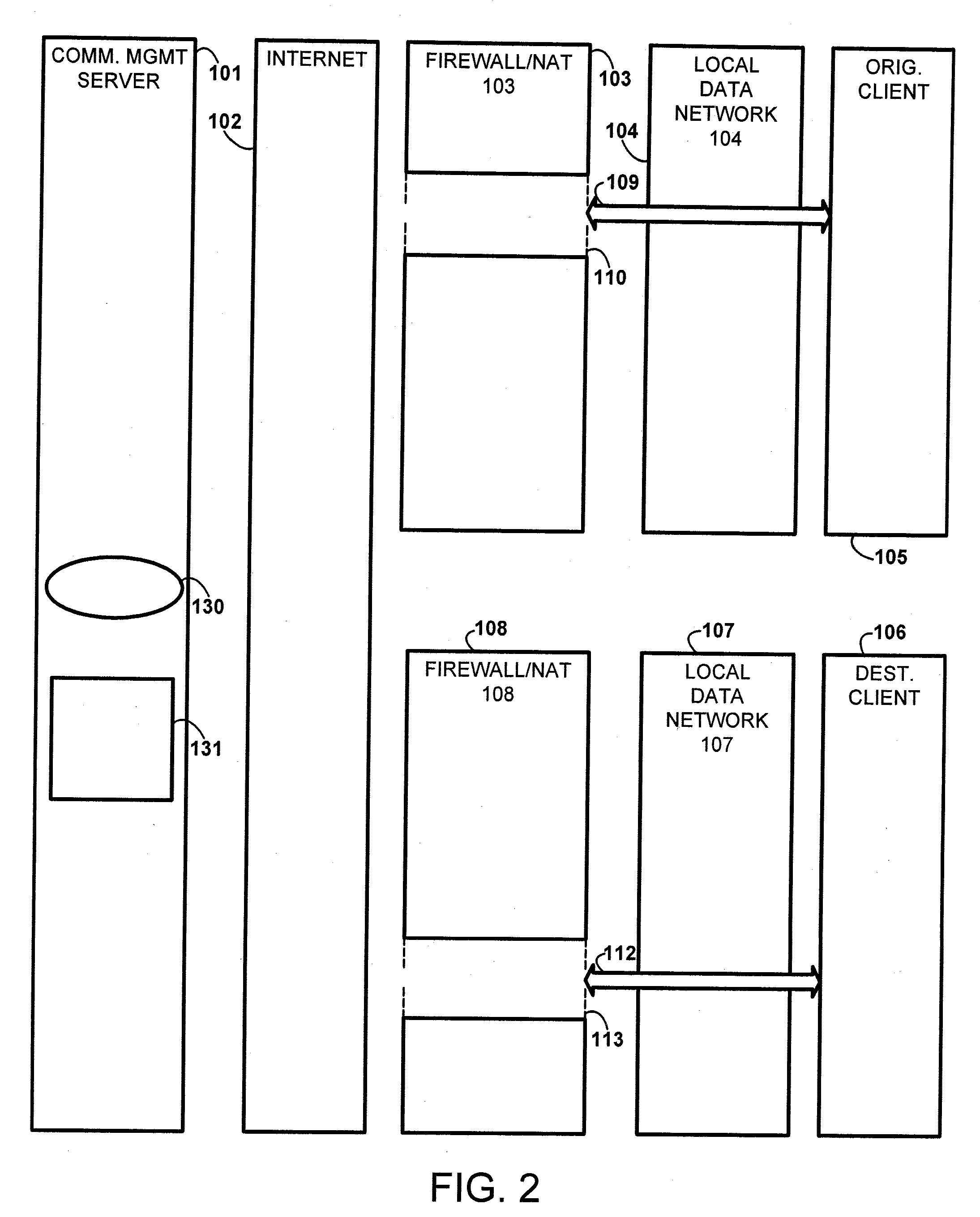
[0029]The novelty of the technology developed according to the present invention is that it allows, in the majority of cases in a client-server network architecture, a client that resides behind a firewall / NAT to exchange RTP media packets directly from another client that can be behind another firewall or on the public network, without requiring the managing server to handle any of the RTP media packets that are exchanged between the clients.

Problems solved by technology

In fact, the client does not even ‘know’ that it resides behind a firewall.

Method used


Image

  • Client-To-Client Direct RTP Exchange In A Managed Client-Server Network
  • Client-To-Client Direct RTP Exchange In A Managed Client-Server Network
  • Client-To-Client Direct RTP Exchange In A Managed Client-Server Network

Examples


Embodiment Construction

[0068]It is to be understood that the description of the present invention is not limited in its application to the details illustrated in the accompanying drawings and is capable of being practiced or carried out in various ways.

Client-to-Client Connection with Each Client Residing Behind a Different Firewall / NAT

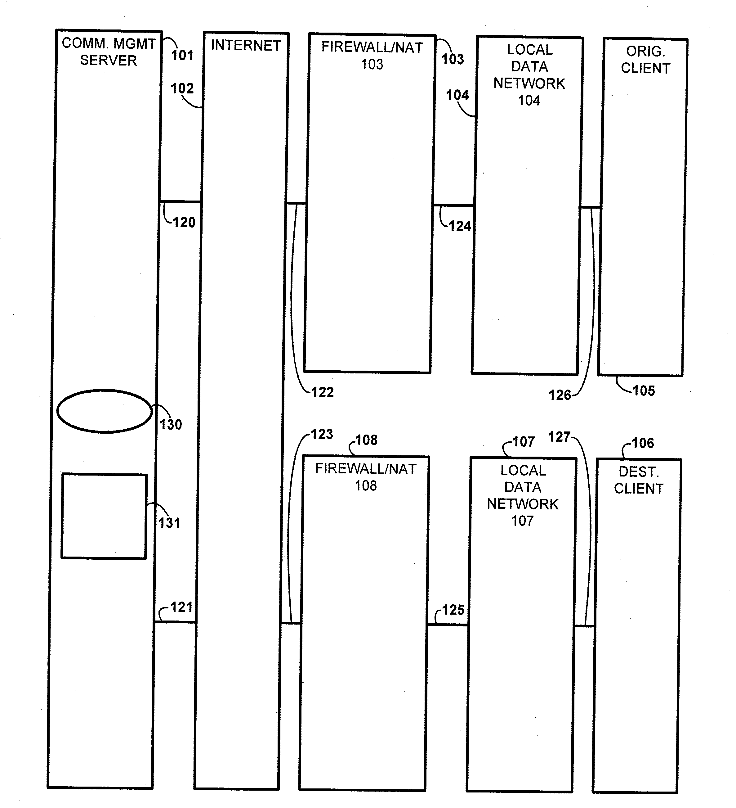
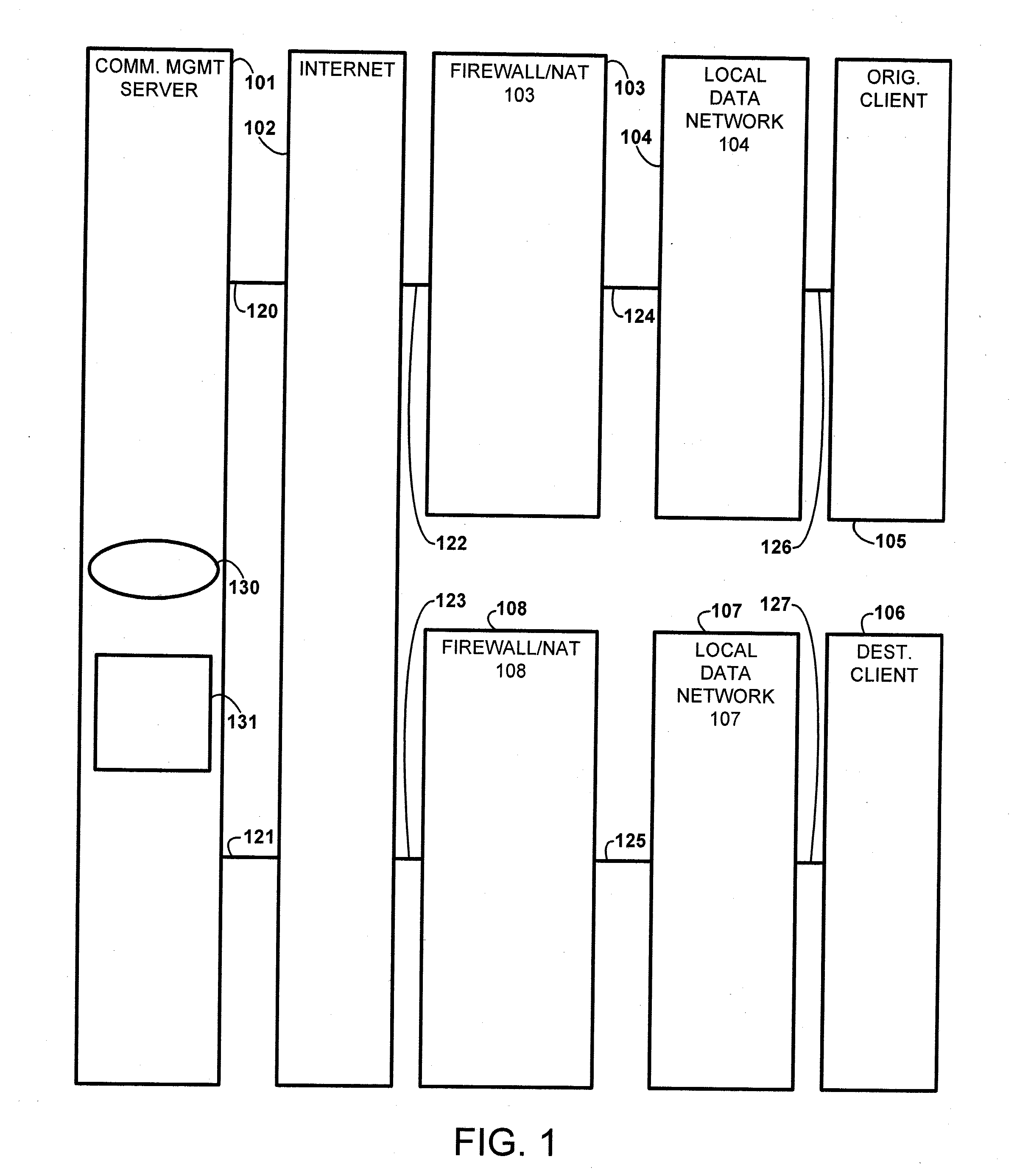
[0069]For the purpose of this discussion, a communications management server (CMS) exists on the Internet. In an embodiment of the present invention, it is assumed that each client resides ‘behind’ a firewall / NAT (there is a firewall between each client and the CMS). Note that this is the most complex scenario. It is possible that only one of the clients resides behind a firewall / NAT. In a common application, the destination client would be a public Internet IP-to-PSTN (Public Service Telephone Network) gateway that converts VoIP calls data (from the originating client) into audio signals compatible with the public telephone network. The gateway would not be located behind ...


PUM


Abstract

A method for establishing a data packet exchange communication session that allows the exchange of data packets between an originating client and a destination client in a data network having a client-server arrangement is provided. An originating client transmits communications session request data message to a communications management server via a first temporary signaling communications path. The communications session request data message contains at least a unique network address of a destination client. The communications management server, upon determining that said originating client is residing behind a first network firewall, determining whether said first network firewall will allow exchange of data packets between said originating client and any other client not residing behind said first network firewall. If it is determined that the first network firewall will allow exchange of data packets between said originating client and any other client not residing behind the first network firewall, the communications management server retrieves relationship information between said unique network address of said originating client and said unique network address of a first network firewall port and a first network firewall port identity, and establishes a data packet exchange communications session with said communications management server through said first network firewall. Otherwise, said communications management server, upon receiving a media packet communications session request data message from said originating client via said first temporary signaling communications path establishes a media packet exchange session with said originating client via said first network firewall.

Description

CROSS REFERENCE TO RELATED APPLICATIONS[0001]The present application claims priority to U.S. provisional application No. 60 / 935,500, filed Aug. 16, 2007, entitled “Client-To-Client Direct RTP Exchange In A Managed Client-Server Network,” the contents of which are hereby incorporated by reference herein in their entirety.FIELD OF THE INVENTION[0002]This invention relates to the field of digital media communications. More particularly, this invention relates to the management of communications sessions between real-time protocol (RTP) media-handling clients in a data network implemented with client-server network architecture.BACKGROUND OF THE ART[0003]In the current state of the art, a managed client-server network uses communications servers to manage RTP media packet exchange between network clients. In a simplified example of a representative process of current art practices, it can be seen that the server not only manages the process of establishing a communications session betwe...

Claims


Application Information

Patent Timeline
IPC IPC(8): G06F15/16
CPCH04L29/12509H04L29/12528H04L61/2567H04L65/608H04L63/029H04L65/1069H04L61/2575H04L65/65
Inventor SMELYANSKY, VLADIMIRGRINBERG, VICTOR
Owner RESTOREN PARTNERS
Learn More