
Temporary protective junction box cover

a junction box and cover technology, applied in the direction of casings/cabinets/drawers, casings/cabinets/drawers details, electrical apparatus, etc., can solve the problems of not protecting the switch or outlet itself, the incoming computer or electrical wire, and the contents of the box from excessive pain

Active Publication Date: 2009-03-19
CRAWFORD JR MCARVIE
View PDF13 Cites 18 Cited by
  • Summary
  • Abstract
  • Description
  • Claims
  • Application Information

AI Technical Summary

Benefits of technology

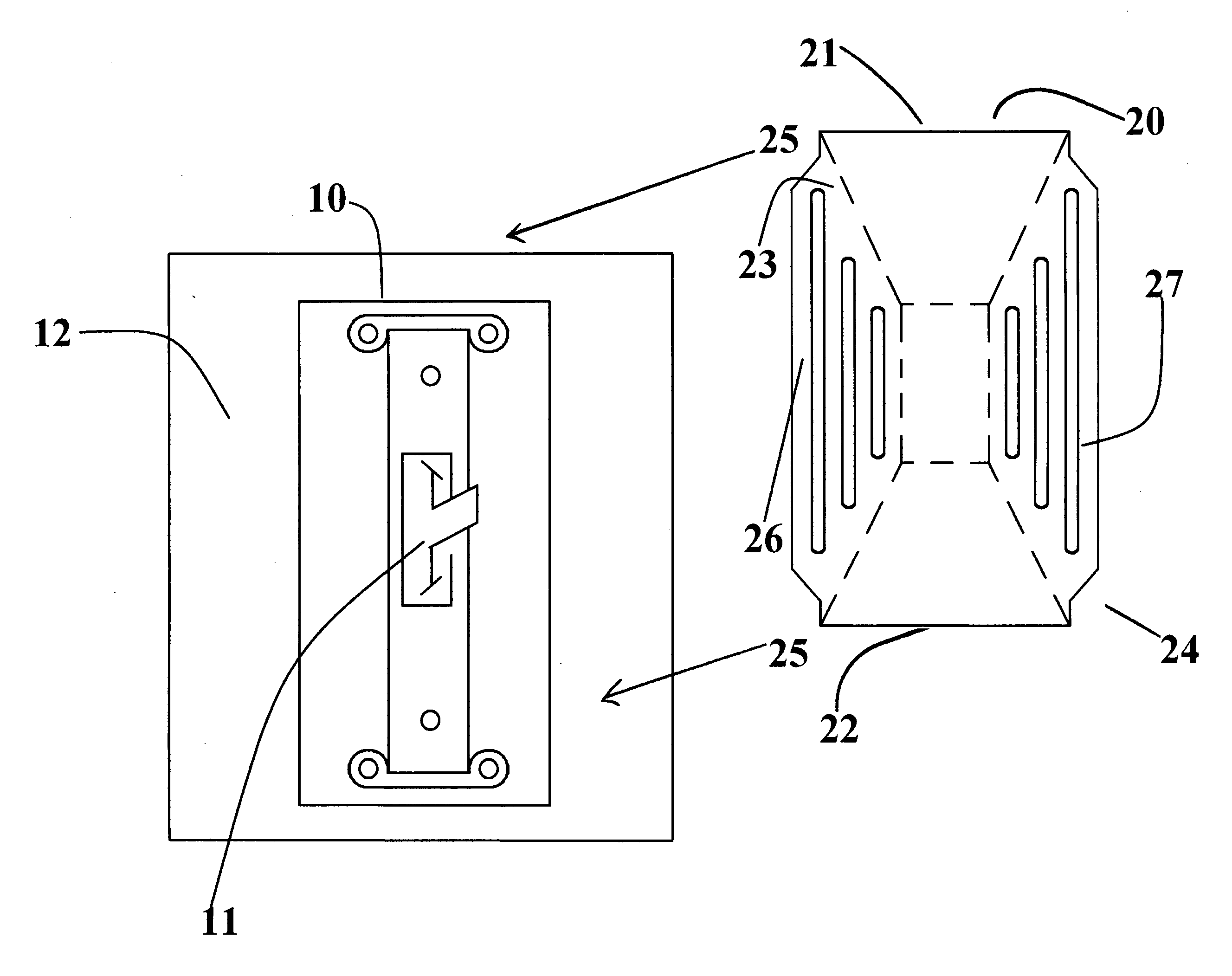
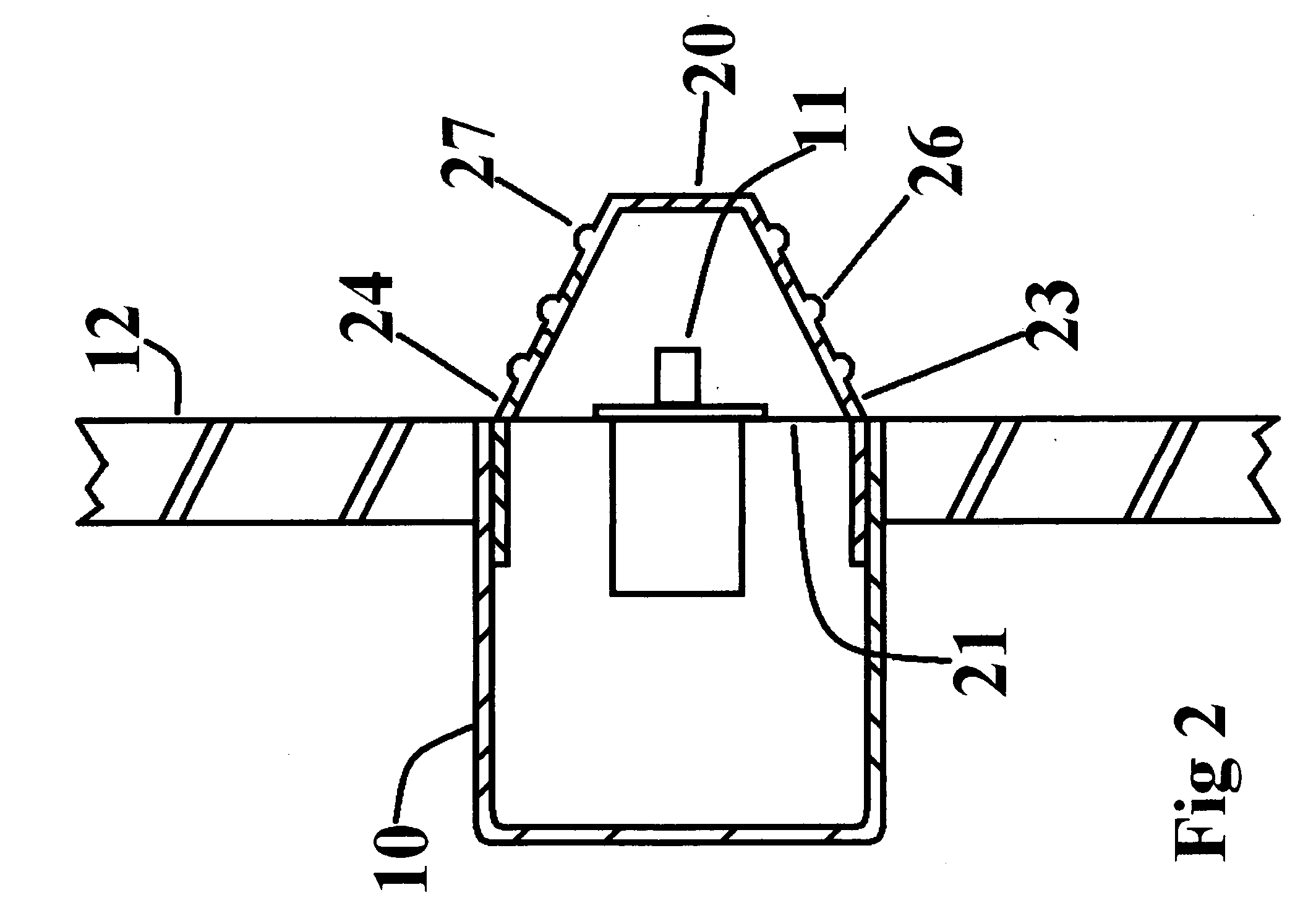
[0007]This idea solves the problem of protecting junction boxes on walls under construction, by simply applying pressure simultaneously to the right and left extending side tabs of the cover, while sliding the cover into the junction box and releasing the pressure on the tabs. The extending side tabs fit snugly against the interior sidewalls of the junction box. The trapezoidal shaped rectangular cover is sized to have a cavity large enough to receive an installed light switch or outlet. The top and bottom edges of the cover rest on the exposed rim of the junction box, allowing the cover to protect the box and it's contents.

Problems solved by technology

If the opening of the junction box and it's contents are exposed, the contents of the box will be prone to damage from excessive paint, joint compound and / or cement stucco.
Masking tape is difficult to apply over protruding light switches.
The method of using masking tape has drawbacks in that if not applied properly it may not protect the switch or outlet itself, or the incoming computer or electrical wires, of from the materials being applied.
Some other drawbacks of using masking tape are, that the tape will leave jagged edges when tape is removed from wall and if an excessive amount of material is applied, the tape's glue may become weak and loose it's adhesion to the switch or outlet, thus allowing the applied materials to attach to and / or damaged either the switch, outlet or cover the electrical wires within the box.

Method used


Image

  • Temporary protective junction box cover
  • Temporary protective junction box cover
  • Temporary protective junction box cover

Examples


Embodiment Construction

[0028]Referring now in greater detail drawings wherein the showings are for the purpose of illustrating preferred embodiments of the invention only, and not for the purpose of limiting the invention.

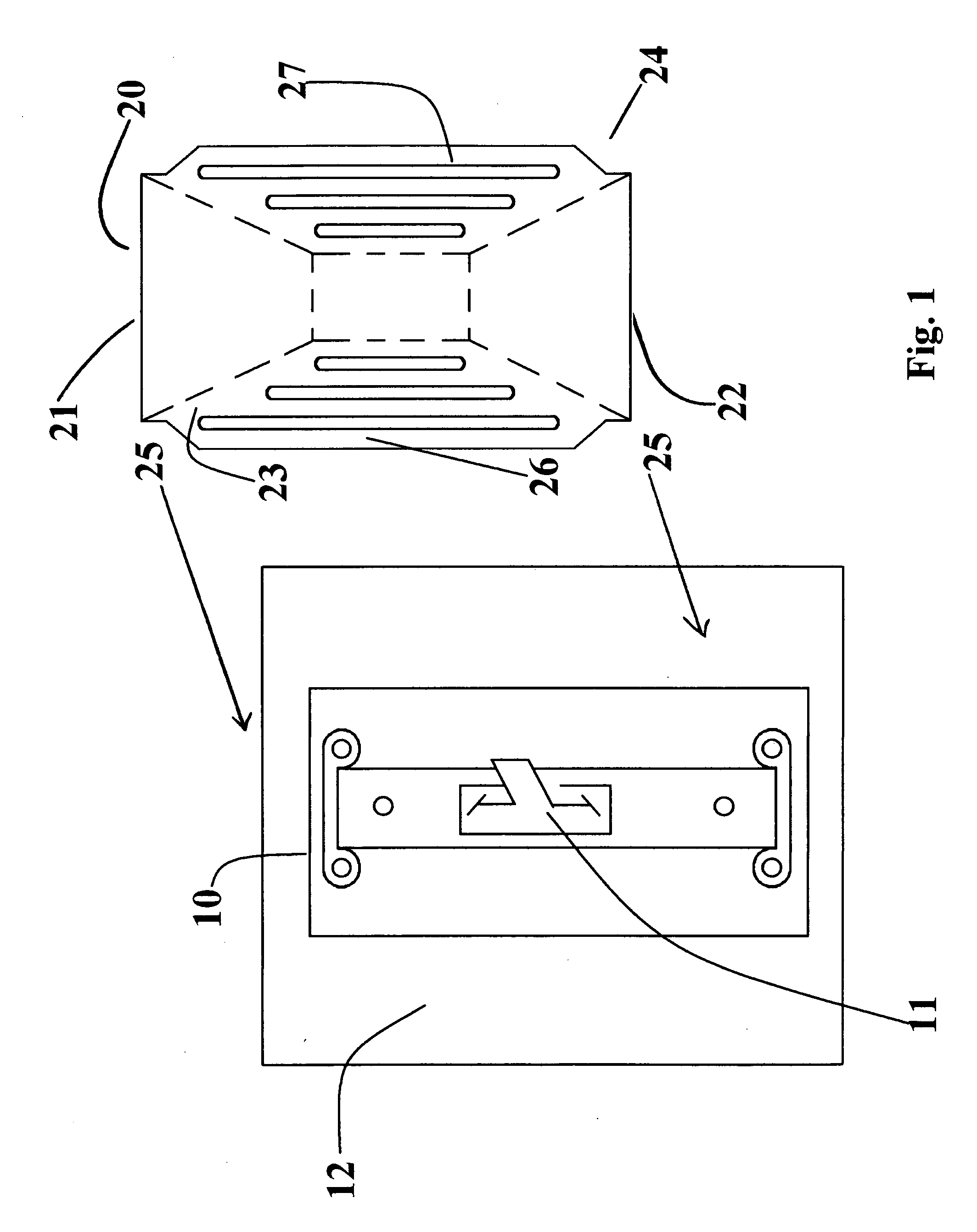
[0029]The first embodiment in accordance with the present invention is shown in FIG. 1-4 and illustrate a temporary outlet cover 20 used to cover a single junction box 10. The outlet cover will be made from a polyethylene material allowing the cover to be durable and reusable.

[0030]Cover 30, 36 and 42 are embodiments for quadruple, triple and double junction boxes. Cover 30, and 42 have rounded grip ridges 33, 34, 38, 39, 45 an 46 that are parallel to top and bottom edges 35, 36, 40, 41, 47 and 48 which allows the installer to have a better grip while installing and removing.

[0031]Cover 50 is an embodiment of the invention for standard round shaped junction boxes and ceiling boxes. The cover has extended side tabs 51 and 52 are circular shaped at the bottom and when pressure is released ...


PUM


Abstract

A temporary protective cover for junction boxes with or without installed switches and / or outlets and for conduit bodies, empty or containing wires or cables of various sizes and uses. The protective cover having a front and rear surface; having a trapezoidal cavity sized to receive installed switches and / or outlets in junction box; the protective cover having two elongated tabs that extend on either side of installed switch or plug inside junction box, for securing the protective cover to junction boxes and conduit bodies; having rectangular or circular cavity opening that is sized to fit openings of junction boxes or conduit bodies, in such a manner that the cover remains fixed relative to the junction box or conduit body.

Description

CROSS-REFERENCE TO RELATED APPLICATIONS[0001]This application claims the benefit from U.S. Provisional Patent Application No. 60 / 958,276 filed Jul. 2, 2007, whose contents are incorporated herein for all purposes.[0002]A temporary protective cover made of flexible, durable, reusable, and solvent resistant plastic for an electrical junction box that can be used during interior and exterior construction of a building. The cover is trapezoidal(pyramid) shaped, has a flat top, and four sides, forming a rectangular opening. The right and left sides of cover are longer, and when squeezed simultaneously the cover will slide into the opening of a junction box. The top and bottom edge of cover will rest flush atop the rim of junction box in order to cover the opening of the box completely. The cover's cavity has a flat top, large enough to receive a protruding light switch. The right and left side tabs extend below rim of junction box. The extended side tabs are long enough to slide into the...

Claims


Application Information

Patent Timeline
IPC IPC(8): H02G3/14
CPCH02G3/12
Inventor CRAWFORD, JR., MCARVIE
Owner CRAWFORD JR MCARVIE
Learn More