
Torsion beam of suspension

a technology of torsion beam and suspension, which is applied in the direction of resilient suspension, interconnection system, vehicle spring, etc., can solve the problems of poor roll stiffness and durability, easy cracks at the connection portions, and deterioration of the durability of the torsion beam by flow, so as to improve durability and increase roll stiffness

Active Publication Date: 2009-01-22
HYUNDAI MOTOR CO LTD +1
View PDF3 Cites 16 Cited by
  • Summary
  • Abstract
  • Description
  • Claims
  • Application Information

AI Technical Summary

Benefits of technology

[0026]Accordingly, an object of the present invention is to provide a torsion beam of a vehicle suspension capable of increasing roll stiffness and of improving durability by changing only a shape of torsion beam.

Problems solved by technology

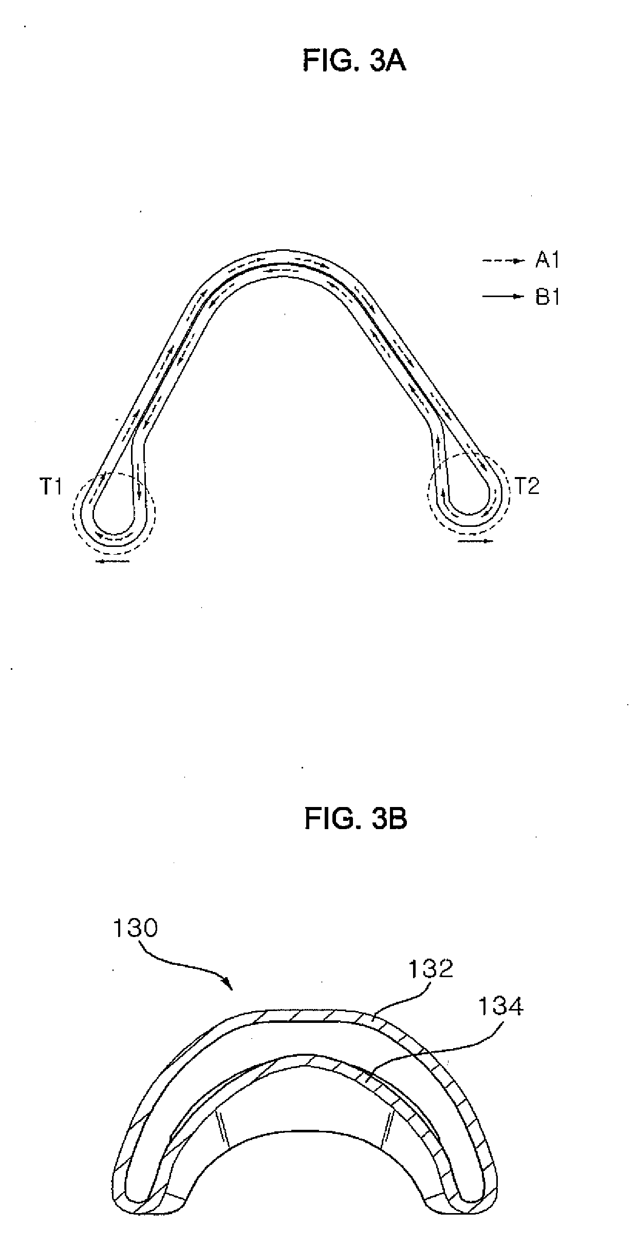
However, in this case, the increased shear flow deteriorates the durability of the torsion beam 130 since the concentration of stress is increased.
These concentrated shear stresses make cracks occur at the connection portions easily.
In other words, as indicated by Arabian numbers in FIGS. 5A to 5C, the roll stiffness and the durability are inferior due to the rolling and the spring reactive force.

Method used


Image

  • Torsion beam of suspension
  • Torsion beam of suspension
  • Torsion beam of suspension

Examples


Embodiment Construction

[0054]Hereinafter reference will now be made in detail to various embodiments of the present invention, examples of which are illustrated in the accompanying drawings and described below. While the invention will be described in conjunction with exemplary embodiments, it will be understood that present description is not intended to limit the invention to those exemplary embodiments. On the contrary, the invention is intended to cover not only the exemplary embodiments, but also various alternatives, modifications, equivalents and other embodiments, which may be included within the spirit and scope of the invention as defined by the appended claims.

[0055]Hereinafter, exemplary embodiments of the present invention will be described in detail with reference to the accompanying drawings.

[0056]FIG. 6 is a perspective view illustrating a torsion beam of a vehicle suspension according to an embodiment of the present invention, FIG. 7 is a sectional view taken along the line F-F of FIG. 6,...


PUM


Abstract

There is provided a torsion beam of a vehicle suspension in which a upper portion and the lower portion of the torsion beam are bent in the front-to-rear direction alone of the vehicle along the longitudinal axis of the torsion beam, and a pair of tails is rounded at both front and rear ends of the torsion beam of the vehicle and formed different from each other in size, a rear tail of the pair of tails which is formed at the rear portion of the vehicle is larger than a front tail formed in the front portion of the torsion beam, the upper and lower portions of the torsion beam are gradually apart from each other with at least two predetermined slopes as they goes from the middle portion to both distal end of the torsion beam. Therefore, roll stiffness is increased and durability is improved.

Description

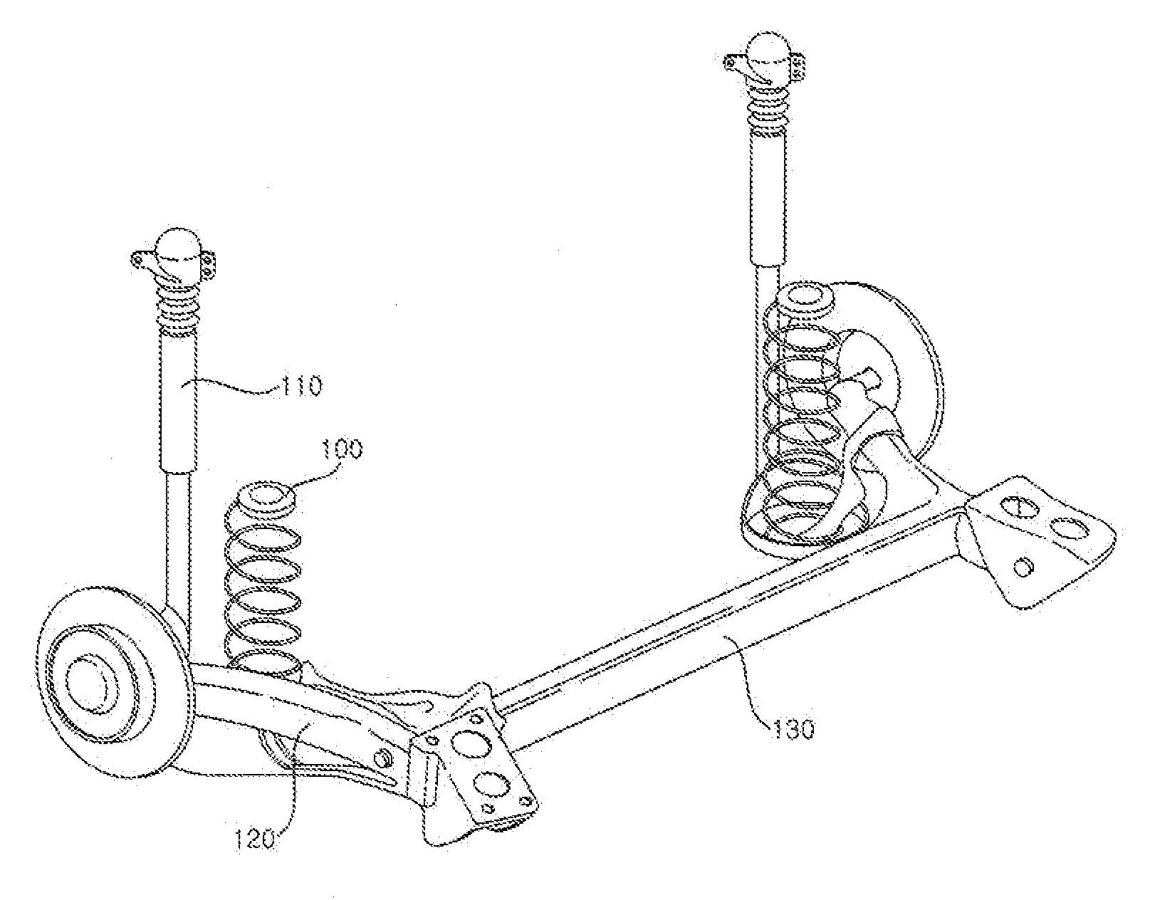
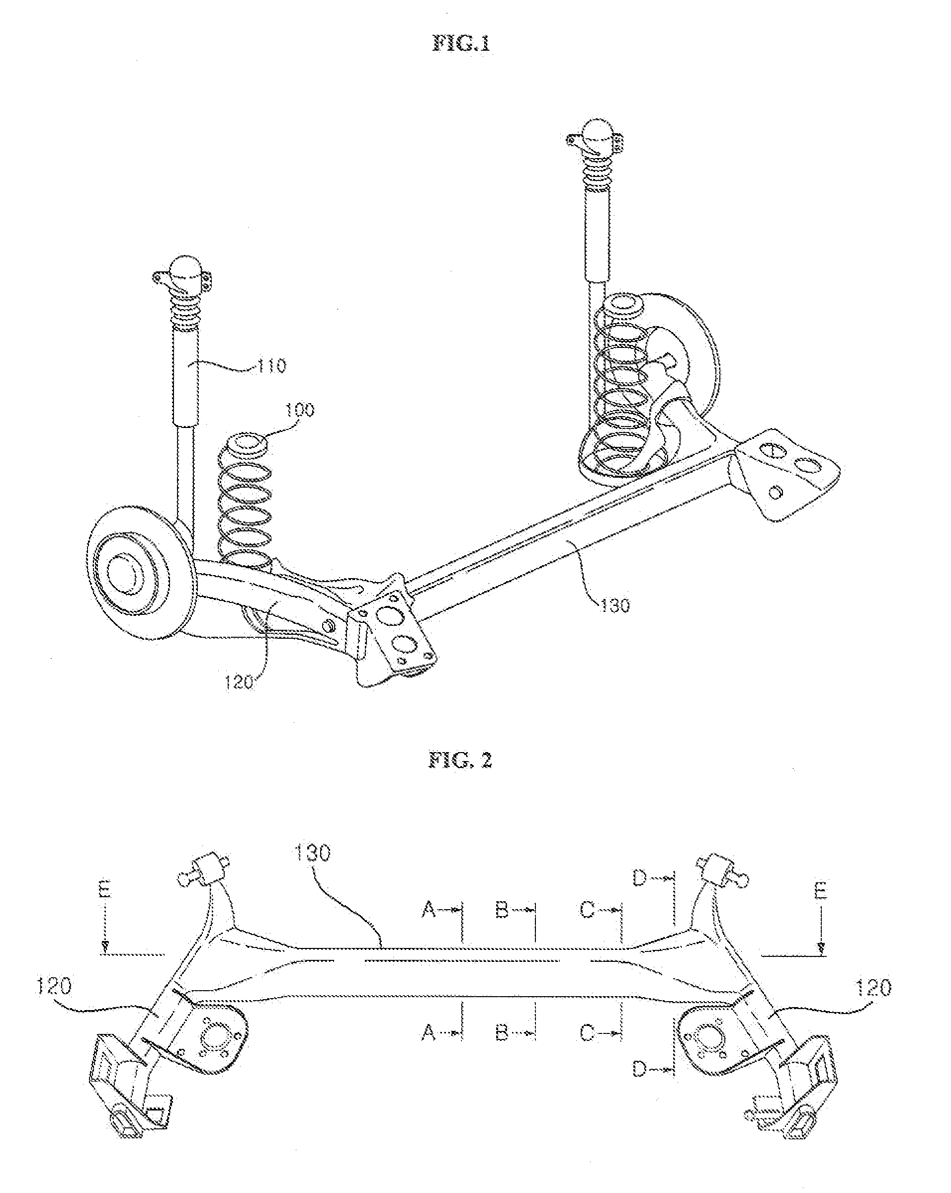
CROSS-REFERENCE TO RELATED APPLICATION[0001]This Nonprovisional application claims priority under 35 U.S.C. §119(a) on Patent Application No. 10-2007-0072932 filed in Korea on Jul. 20, 2007, the entire contents of which are hereby incorporated by reference.BACKGROUND OF THE INVENTION[0002]1. Field of the Invention[0003]The present invention relates to a torsion beam of a suspension of a vehicle, and more particularly, to a torsion beam of a suspension of a vehicle having a larger diameter of a rear tail than that of a front tail.[0004]2. Description of the Background Art[0005]As illustrated in FIG. 1, a suspension of a vehicle connects a vehicle body to wheels and absorbs shock and vibration applied from a road during traveling to improve a ride comfort and stability of the vehicle.[0006]The suspension is categorized into an integrated type for connecting right and left wheels to each other by an axle and an independent type in which the right and left wheels are independently drive...

Claims


Application Information

Patent Timeline
Patent Type & Authority Applications(United States)
IPC IPC(8): B60G21/05
CPCB60G21/051B60G2200/21B60G2200/446B60G2202/136B60G2206/81B60G2206/20B60G2206/202B60G2206/203B60G2206/012B60G11/18B60G7/00
Inventor LEE, JAE YOUN
Owner HYUNDAI MOTOR CO LTD
Learn More