Fastening device for flat components, especially solar modules, to be arranged on a framework

a technology of fixing device and flat component, which is applied in the direction of solar heat collector mounting/support, photovoltaics, solar heat collectors for particular environments, etc., can solve the problem of reducing the maximum active surface area of solar modules that can be placed on the given base surface area, and achieves simple fixation and facilitate sealing the effect of the area

Inactive Publication Date: 2008-12-25
FATH GMBH
View PDF11 Cites 51 Cited by
  • Summary
  • Abstract
  • Description
  • Claims
  • Application Information

AI Technical Summary

Benefits of technology

[0015]In particular, in such an arrangement, but also when the components are not offset and overlapped but are arranged plane-parallel, it is useful to provide on the profile element that runs horizontally on the bottom in the assembled position and that is embodied as a profile rail a sealing element that continues when needed in the profile connector provided when needed, and against which in the assembled position, the edge of the component arranged therebeneath is positioned. This advantageously facilitates sealing in the area of the horizontal gap between two components.
[0016]In order to provide a sealing option in the longitudinal direction, as well as to avoid moisture being drawn downward by the capillary gap that results with the (nearly) touching components in the area of the longitudinal lateral edges, usefully provided between two mutually opposing profile elements is a profile component that extends longitudinally relative to the assembled position, and that runs beneath the transition gap between two adjacent components, and that where n

Problems solved by technology

In this manner, each individual component is fastened or screwed on individually, which is very complex during assembly and also during disassembly, for instance, if one component must be exchanged because of a defect.
For instance, in the case of a solar module it would not be possible to place the retaining part directly on the upper glass plate since this could cause damage to

Method used


Image

  • Fastening device for flat components, especially solar modules, to be arranged on a framework
  • Fastening device for flat components, especially solar modules, to be arranged on a framework
  • Fastening device for flat components, especially solar modules, to be arranged on a framework

Examples


Embodiment Construction

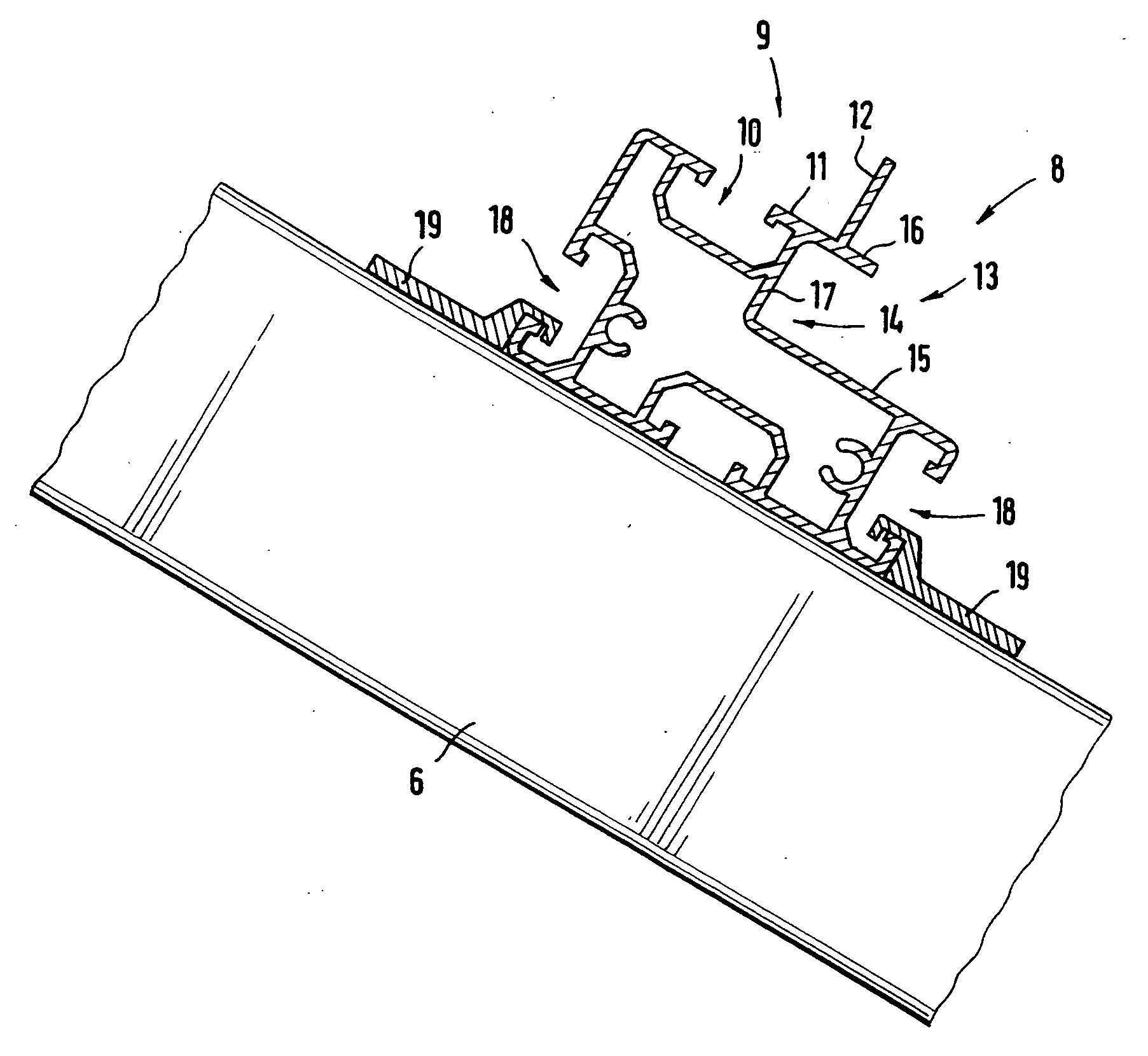
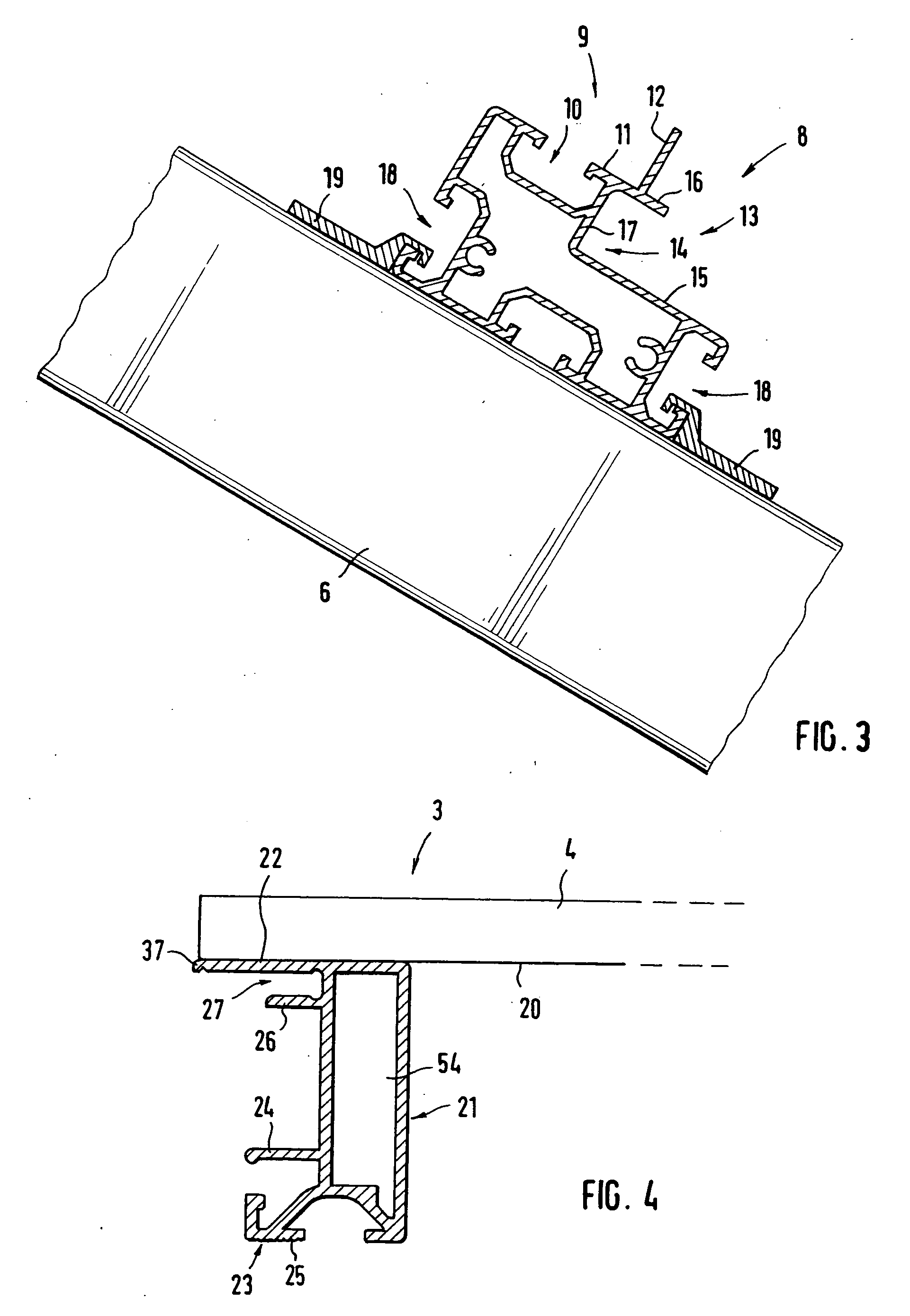
[0031]FIG. 1 depicts the principle of a component group 2 arranged on a house roof 1 and including, merely as an example, six components 3, e.g., in the form of solar modules 4 including a plurality of solar cells for producing energy. Provided for retaining the solar modules 4, is a framework 5 that includes two rails 6, running vertically in this case, that are fixed to the roof via corresponding roof retaining elements 7. Two profile mounting rails 8 are arranged on the rails 6 of the framework via fastening means (not shown in greater detail). The two profile mounting rails 8 run spaced apart from, and parallel to, one another and cross the rails 6 horizontally. As will be explained in greater detail in the following, they are part of a fastening device for the solar modules 4, which are themselves fastened to the profile mounting rails 8 via suitable profile elements and retaining elements. At this point it should be noted that, of course, far more than six solar modules can be...


PUM


Abstract

A fastening device for flat components, especially solar modules, to be arranged on a framework, includes a first profile mounting rail and a second profile mounting rail that are spaced apart from one another and that are arranged horizontal and parallel on the framework and on which one component can be affixed in the area of its mutually opposing edges. Profile elements, which are arranged on the bottom of a frameless component in the area of the lateral edges, are provided with a retaining rib which projects toward the lateral edge, and connect to the profile mounting rails. A retaining element is provided with a first fastening segment for fastening to a fastening area of the profile mounting rail and with a second fastening segment having two retaining segments that project to both sides and that, in the assembled position, overlap the mutually opposing retaining ribs of two components to be placed next to one another.

Description

BACKGROUND OF THE INVENTION[0001]The invention relates to a fastening device for flat components, especially solar modules, to be arranged on a framework, and includes a first profile mounting rail and a second profile mounting rail that are spaced apart from one another and that are to be arranged horizontal and parallel on the framework, and on which one component can be affixed in the area of its mutually opposing edges.[0002]Flat components such as, for instance, solar modules or solar collectors, etc., are normally arranged outside, whether free-standing or on the roofs of houses, on a framework. The framework itself is normally anchored in the ground or on the roof and comprises, for instance, appropriate lateral guides formed from appropriate profile rails, to which the components are fixed via a suitable fastening device. Such a fastening device normally includes two parallel profile rails that are to be arranged parallel to, and spaced apart from, one another on the framewo...

Claims


Application Information

Patent Timeline
IPC IPC(8): F24J2/46
CPCF24J2/465H02S20/23F24J2/5211F24J2/5254F24J2/5256F24J2002/0061F24J2002/4661F24J2002/5215F24J2002/5226F24J2002/529Y02B10/12Y02B10/20Y02E10/47Y02E10/50H02S20/00F24J2/5207F24S25/20F24S25/35F24S25/632F24S25/634F24S80/70F24S2020/13F24S2025/018F24S2025/019F24S2025/6002F24S2025/801F24S2025/807Y02B10/10
Inventor FATH, JAN MIRKO
Owner FATH GMBH
Why Eureka
Try Eureka