Computer-Aided Method for Detection of Interval Changes in Successive Whole-Body Bone Scans and Related Computer Program Program Product and System

a computer program and interval change technology, applied in the field of image production, can solve the problems of difficult to detect subtle changes between two successive abnormal bone scans, time-consuming to identify multiple lesions, and sensitivity of bone scan examination for detection

Inactive Publication Date: 2008-12-04
SHIRAISHI JUNJI +4
View PDF3 Cites 32 Cited by
  • Summary
  • Abstract
  • Description
  • Claims
  • Application Information

AI Technical Summary

Problems solved by technology

Although the sensitivity of bone scan examinations for detection of bone abnormalities has been considered to be very high, it is time-consuming to identify multiple lesions such as bone metastases of prostate and breast cancers.
In addition, because of variations in patient conditions, the accumulation of radioisotopes during each examination, and the image quality of gamma cameras, it is difficult to detect subtle changes between two successive abnormal bone scans.
The sensitivity of bone scan examinations for detection of bone abnormalities has been considered to be very high; however, it is time-consuming to identify multiple lesions such as bone metastases of prostate and breast cancers.
In addition, because of variations in patient conditions, the accumulation of radioisotopes during each examination, and the image quality of gamma cameras, it is difficult to detect subtle changes between two successive abnormal bone scans.
Several temporal subtraction techniques have been applied to chest radiographs [5-8], chest CT images [9], and brain MRI images [10]; however, to the inventor's knowledge there has been no application of a temporal subtraction scheme by use of the nonlinear image-warping technique for bone scintigrams.
In addition, to the inventor's knowledge there has been no approach to developing a computer-aided diagnostic (CAD) method for the detection of interval changes in successive bone scans and in other images obtained from any diagnostic nuclear medicine procedures.

Method used


Image

  • Computer-Aided Method for Detection of Interval Changes in Successive Whole-Body Bone Scans and Related Computer Program Program Product and System
  • Computer-Aided Method for Detection of Interval Changes in Successive Whole-Body Bone Scans and Related Computer Program Program Product and System
  • Computer-Aided Method for Detection of Interval Changes in Successive Whole-Body Bone Scans and Related Computer Program Program Product and System

Examples


Embodiment Construction

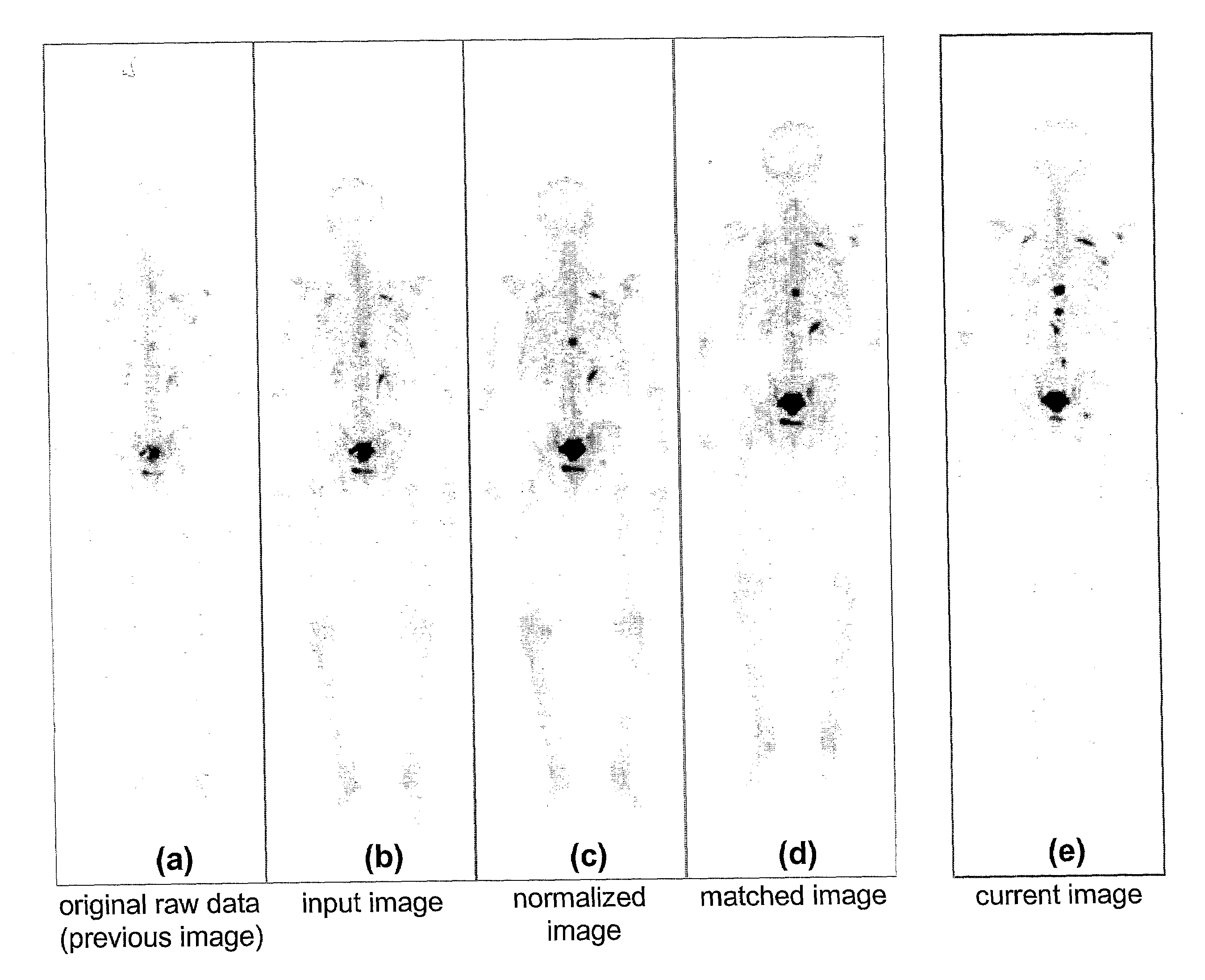
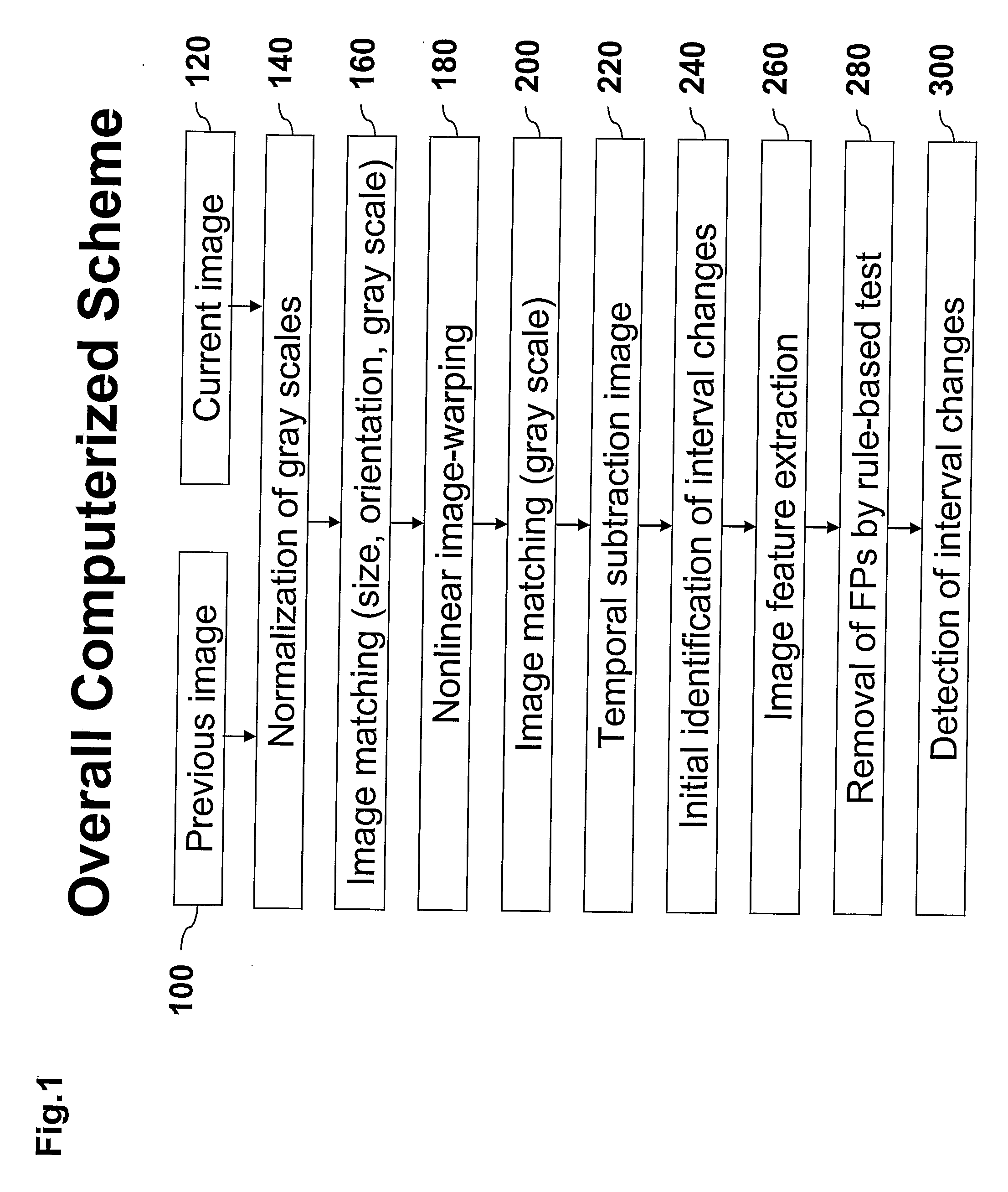
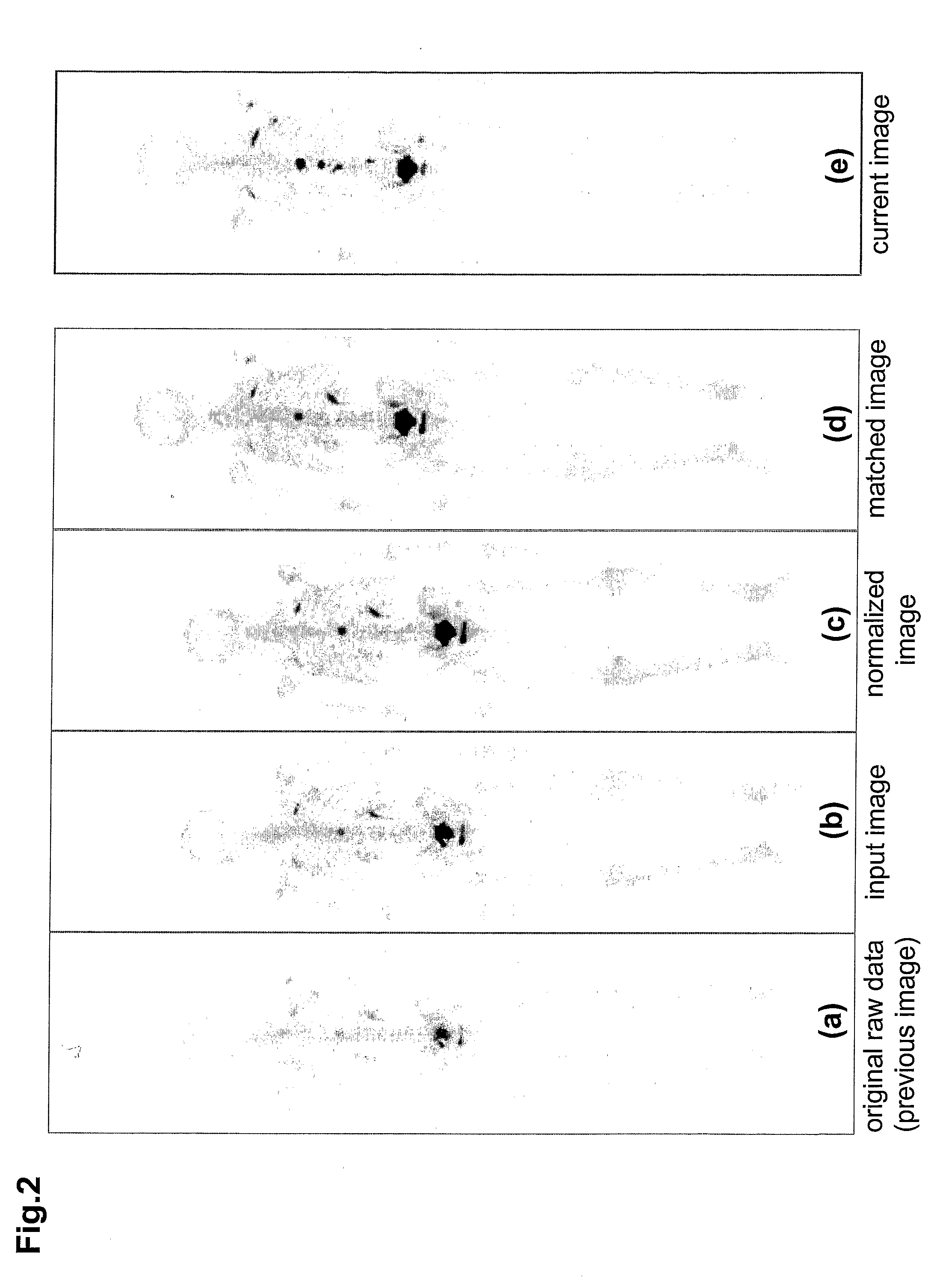
[0057]One embodiment of a computerized method for the production of images to aid in the detection of the change in the progress of a disease in a patient is discussed herewith. For example, in one embodiment of the present invention a new computer-aided diagnostic (CAD) method for the detection of interval changes in successive whole-body bone scans by use of a temporal subtraction image was developed, FIG. 15 illustrates an example of a full body scan. The method uses a nonlinear image-warping technique. Fifty-eight pairs of successive bone scans were carried out in which each scan included both posterior and anterior views obtained simultaneously by use of a set of two gamma cameras placed face-to-face. Inclusion criteria for these cases, which were selected from a total of 1038 bone scintigrams (examined in 2004), were; 1) at least one abnormal finding in either view, 2) a maximum number of 20 interval changes, and 3) one image pair per patient. As shown in FIG. 15, it was deter...


PUM


Abstract

A method of producing an image to aid detection of a change in progress of a disease in a patient is described. In the method, a first image of a distribution of a radioisotope in the patient is obtained. A second image of the distribution of the radioisotope in the patient is also obtained. At least one of the first and second images are then normalized (1:140). One of the images is warped to match the other image using a multiple-segment matching method (1:160). The first image is subtracted from the second image to form a subtraction image (1:220). Finally, the resulting subtraction image is displayed.

Description

CROSS-REFERENCE TO RELATED APPLICATIONS[0001]The present application claims priority to Provisional Application No. 60 / 738,982 filed Nov. 23, 2005, the contents of which are incorporated herein by reference.STATEMENT REGARDING FEDERALLY SPONSORED RESEARCH[0002]The present invention was made in part with U.S. Government support under USPHS Grant Nos. CA062625 and CA098119. The U.S. Government may have certain rights to this invention.BACKGROUND OF THE INVENTIONField of the Invention[0003]The present invention relates generally to the production of images to aid in the detection of the change in the progress of a disease in a patient.[0004]The present invention also generally relates to computerized techniques for automated analysis of digital images, for example, as disclosed in one or more of U.S. Pat. Nos. 4,839,807; 4,841,555; 4,851,984; 4,875,165; 4,918,534; 5,072,384; 5,150,292; 5,224,177; 5,289,374; 5,319,549; 5,343,390; 5,359,513; 5,452,367; 5,463,548; 5,491,627; 5,537,485; 5,...

Claims


Application Information

Patent Timeline
IPC IPC(8): G06K9/00
CPCG06T5/50G06T7/0012G06T7/0026G06T2207/30008G06T7/32
Inventor SHIRAISHI, JUNJIDOI, KUNIOAPPELBAUM, DANIELPU, YONGLINLI, QIANG
Owner SHIRAISHI JUNJI
Why Eureka
Try Eureka