
Apparatus for controlling aircraft ground movement

Active Publication Date: 2008-12-04
BOREALIS TECH LTD
View PDF8 Cites 18 Cited by
  • Summary
  • Abstract
  • Description
  • Claims
  • Application Information

AI Technical Summary

Benefits of technology

[0012]It would be advantageous to have a means for controlling the movements of an aircraft on the ground. It would be further advantageous for this means to be remote from said aircraft and to be operable by airport ground staff.
[0015]It is a further object of the invention to provide said means which are intuitive, safe, and easy to operate.
[0016]An apparatus for controlling the movement of an aircraft having a self-propelled nosewheel, on the ground, is disclosed. The apparatus comprises a control arm; a control unit; means for transmitting information to said self-propelled nosewheel; means for receiving information at said self-propelled nosewheel; and means for controlling at least one of the speed and direction of said nosewheel; whereby airport ground staff can intuitively control the movements of said aircraft by holding said arm and moving it in the direction of required movement of said aircraft.

Problems solved by technology

However, this magnetic field configuration induces substantial rotor currents in the rotor windings, and the currents produce induction based torque to rotate the rotor.

Method used


Image

  • Apparatus for controlling aircraft ground movement
  • Apparatus for controlling aircraft ground movement
  • Apparatus for controlling aircraft ground movement

Examples


first embodiment

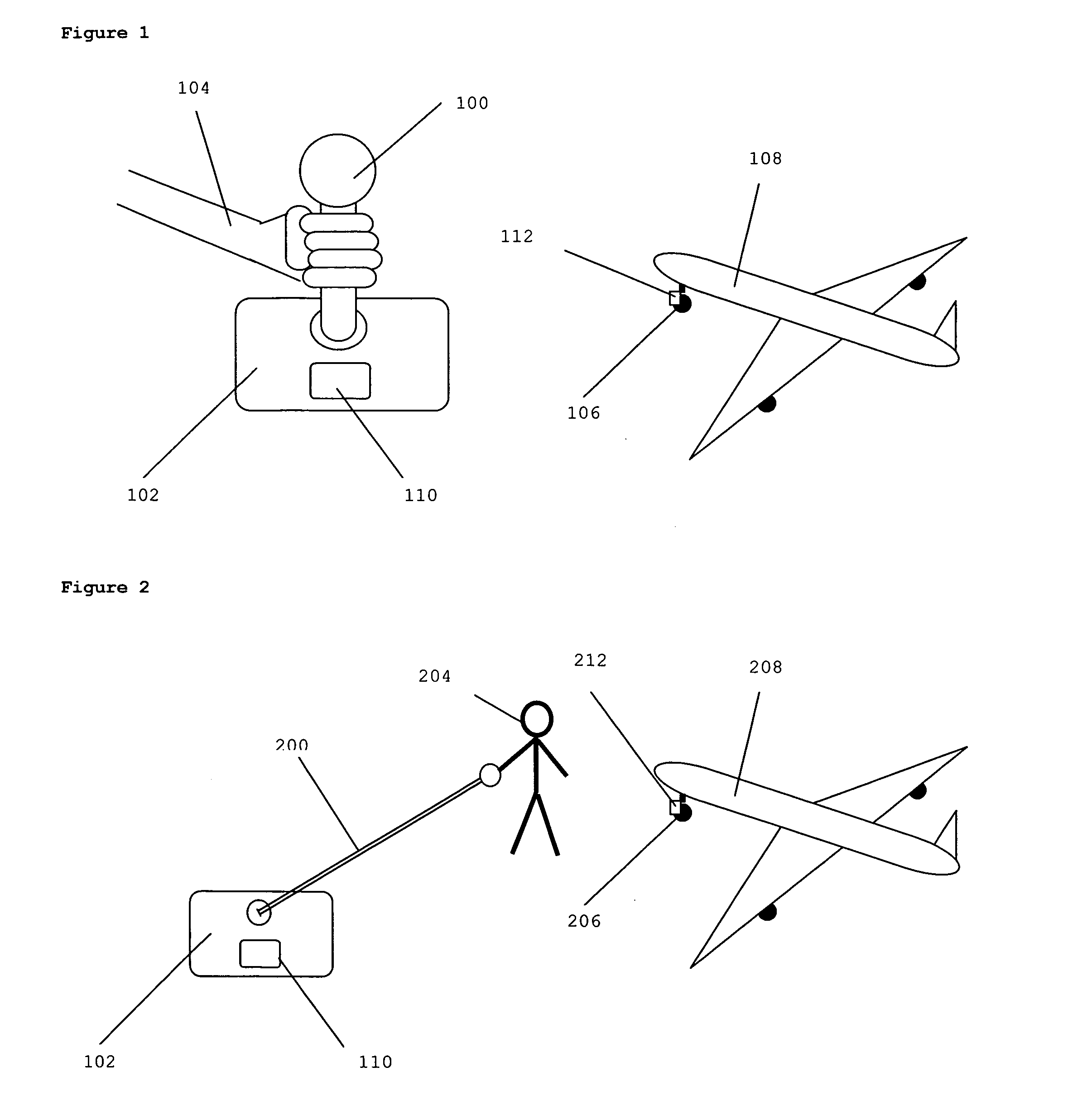
[0025]FIG. 1 shows the invention in which the control arm, control unit and means for transmitting information are remote from said aircraft and said control arm is short. Short is defined herein as shorter than a length at which a member of ground staff can walk comfortably at least one step in any direction while holding said control arm. Control arm 100 is moveably attached at its base to control unit 102, such that it can be moved by ground staff member 104. Movements of arm 100 are transmitted via transmitter 110 to receiver 112 in the self-propelled nosewheel 106 of aircraft 108, which moves according to the movements of control arm 100.

[0026]Said arm is preferably less than 0.5 m long. An advantage of this is that it can easily be manipulated while a controller stands in one location. More preferably, said arm is 0.1-0.2 m long. An advantage of this is that it can be manipulated while the heel of the operator's hand remains in one location. The arm may also be a few millimete...

second embodiment

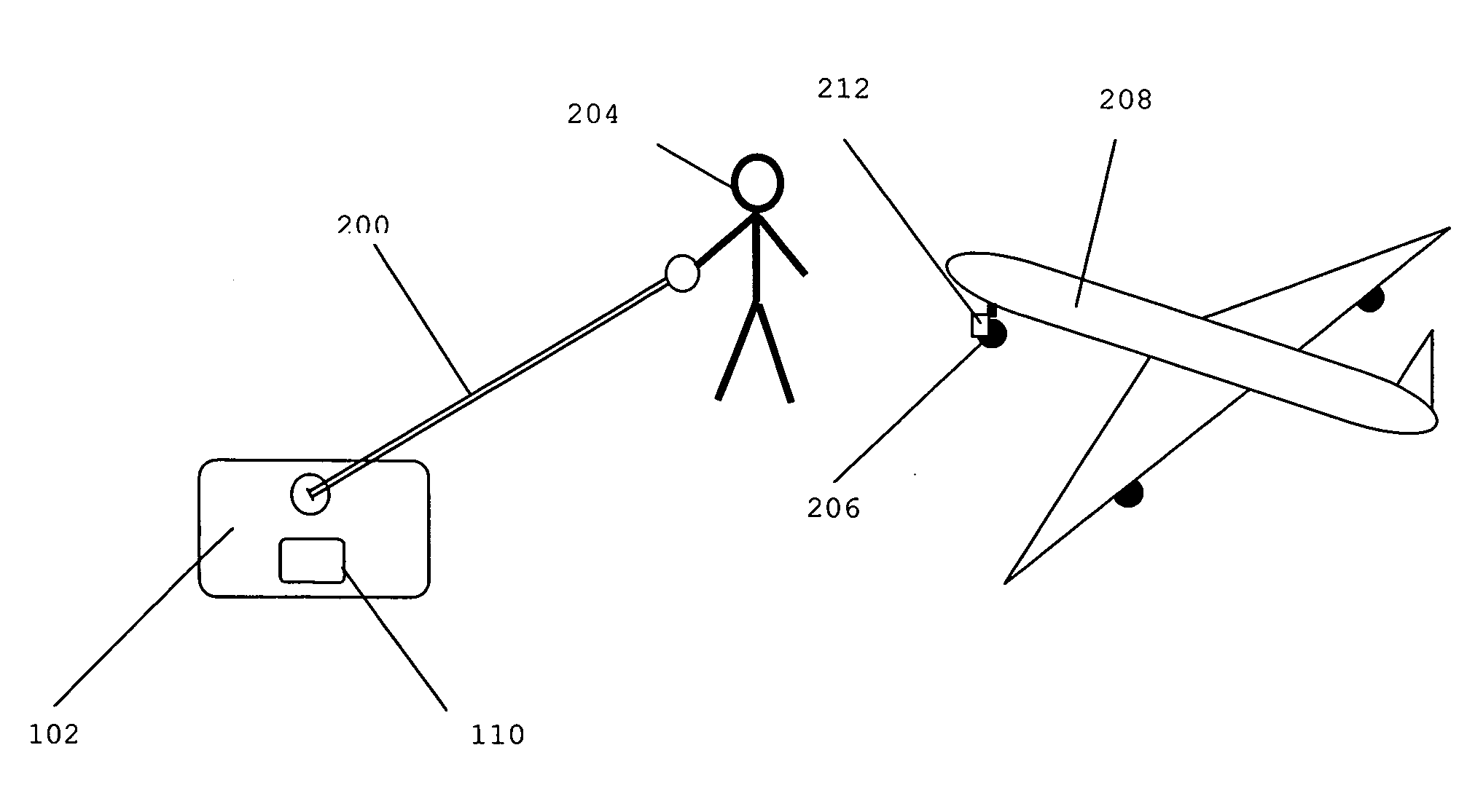
[0046]In the invention, shown in FIG. 2, the control arm, control unit and means for transmitting information are remote from said aircraft and said control arm is long. Long is defined herein as of sufficient length that a member of ground staff can walk comfortably at least one step in any direction while holding said control arm.

[0047]FIG. 2 shows the second embodiment of the invention. Long control arm 200 is moveably attached at its base to control unit 202, such that it can be moved by ground staff member 204 who walks while holding said arm. Movements of long control arm 200 are transmitted via transmitter 210 to receiver 212 in the self-propelled nosewheel 206 of aircraft 208, which moves according to the movements of control arm 200.

[0048]Said arm is preferably greater than 0.5 m in length. An advantage of this is that a ground staff member can walk comfortably at least one step in any direction while holding said control arm. This is a sensitive and intuitive way to contro...

third embodiment

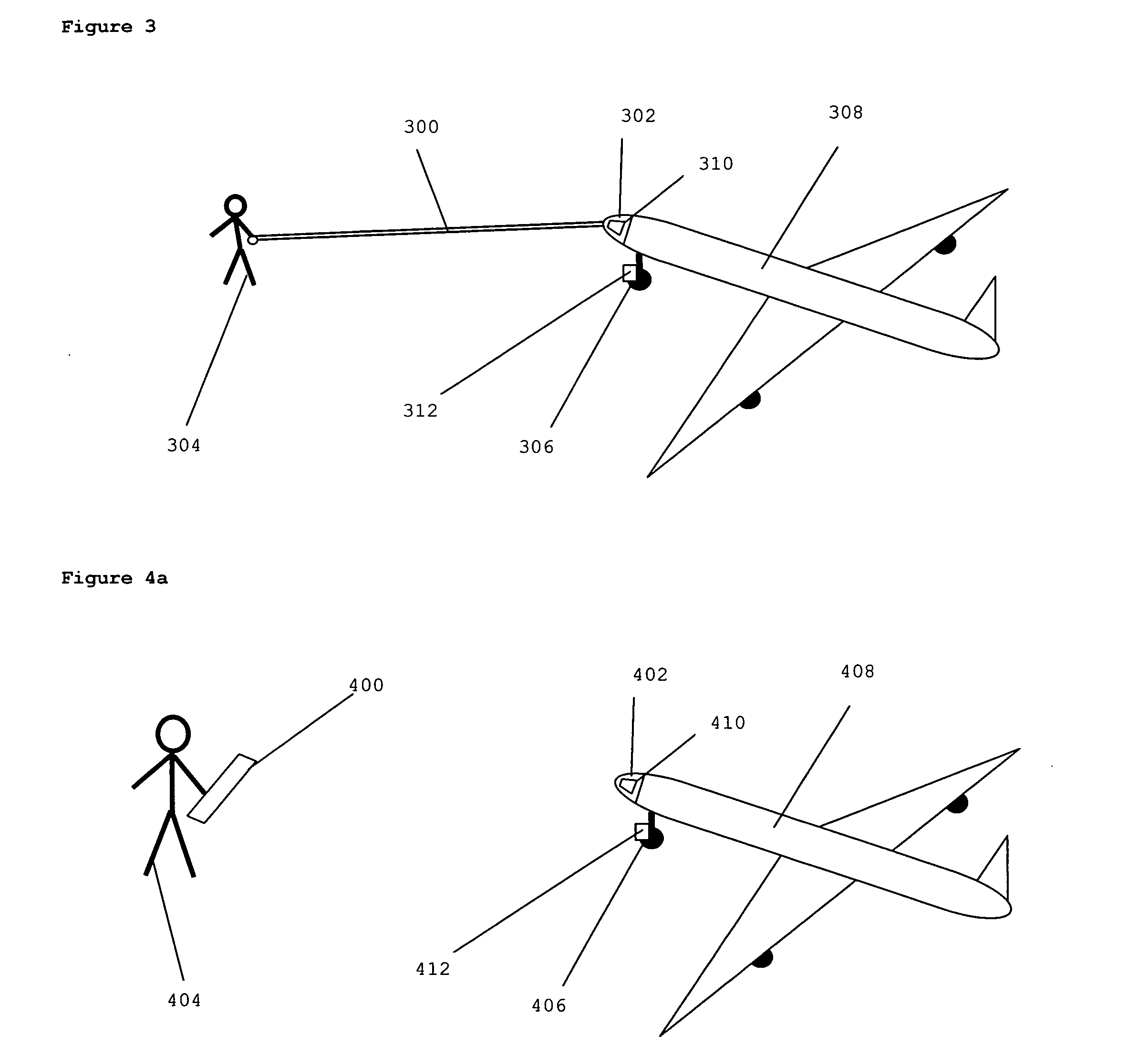
[0052]In the invention shown in FIG. 3, the control arm, control unit and means for transmitting information are attached to said aircraft and said control arm is long.

[0053]FIG. 3 shows the third embodiment of the invention. Long control arm 300 is moveably attached at its base to control unit 302, such that it can be moved by ground staff member 304 who walks while holding said arm. Movements of long control arm 300 are transmitted via transmitter 310 to receiver 312 in the self-propelled nosewheel 306 of aircraft 308, which moves according to the movements of control arm 300.

[0054]Said arm, control unit and means for transmitting information (hereafter called the ‘aircraft-moving apparatus’) are preferably attached to a point at the front of the aircraft from which they can be easily reached by said ground staff member, such as the lower part of the fuselage at the front of the aircraft, or a part of the nosewheel strut or other undercarriage apparatus. An advantage of this is th...


PUM


Abstract

An apparatus for controlling the movement of an aircraft having a self-propelled nosewheel, on the ground, is disclosed. The apparatus comprises a control arm; a control unit; means for transmitting information to said self-propelled nosewheel; means for receiving information at said self-propelled nosewheel; and means for controlling at least one of the speed and direction of said nosewheel; whereby airport ground staff can intuitively control the movements of said aircraft by holding said arm and moving it in the direction of required movement of said aircraft.

Description

CROSS-REFERENCE TO RELATED APPLICATIONS[0001]This application claims the benefit of U.S. Provisional Patent Application No. 60 / 958,602, filed Jul. 5, 2007. This application is a Continuation-in-Part of International Application PCT / US2007 / 019054, filed Aug. 29, 2007, and which designates the United States, which international application was published on Apr. 24, 2008, as International Publication WO08048393 in the English language. International Application No. PCT / US2007 / 019054 claims the benefit of GB Patent Application No. 0616984.1 filed on Aug. 29, 2006, and of U.S. Provisional Patent Application No. 60 / 958,602 filed on Jul. 5, 2007.BACKGROUND OF THE INVENTION[0002]Motors providing high torque at low speeds are known in the art. Specifically, such motors are known that are designed for the purpose of propelling aircraft on the ground.[0003]WO05112584 to Edelson discloses a motor-generator machine comprising a slotless AC induction motor. The motor disclosed therein is an AC in...

Claims


Application Information

Patent Timeline
Patent Type & Authority Applications(United States)
IPC IPC(8): B64C25/50
CPCY10S180/904B64F1/22B64C25/405Y02T50/823Y02T50/80B62D1/00B62D1/283B64C25/02B64C25/50B64F1/00B64F1/12B64F5/00
Inventor EDELSON, JONATHAN SIDNEYCOX, ISAIAH WATASBARBALATA, DANIEL LIVIU
Owner BOREALIS TECH LTD
Learn More