
Cardiopulmonary bypass devices and methods

a technology of cardiopulmonary bypass and bypass device, which is applied in the field of cardiopulmonary bypass device and method, can solve the problems of heart failure, heart failure, defibrillation and drugs that do not address the underlying cause, and the heart is simply too compromised to be restarted, so as to achieve the effect of most cell death and subsequent irreversible organ damage, and the cell death of the cell

Inactive Publication Date: 2008-11-27
LAERDAL MEDICAL AS
View PDF33 Cites 16 Cited by
  • Summary
  • Abstract
  • Description
  • Claims
  • Application Information

AI Technical Summary

Problems solved by technology

One other factor of survival is that current treatment of chest compressions, ventilations, defibrillation and drugs does not address the underlying cause of the arrest.
Some hearts are simply too compromised to be restarted, even though CPR, drugs and defibrillation are delivered according to best practice.
Given the situation of sudden cardiac arrest, most of the cell death and subsequent irreversible organ damage may take place when perfusion is restored because of the circulation of toxic components that have built up during ischemia.
Cooling also seems to slow down the speed of cell death caused by reperfusion after cardiac arrest.
There are, however, limits to this method.
The person performing CPR may not be sufficiently skilled or motivated, there are difficulties performing CPR in an ambulance, there may not be enough rescuers available to perform CPR while performing other necessary activities at the same time, it is difficult to perform CPR over a long period of time, and the effectiveness of CPR to generate flow is also reduced by time.
Such traditional machines are typically not suited for emergency use, as they are not portable, they require particular skills to operate and are not easily transported to the location where a cardiac arrest or trauma victim is located.
The oxygenator is a risk factor of these apparatuses, as the blood is exposed to a huge surface area of the oxygenator and may coagulate.
The oxygenator is also large and makes the apparatus large and complex and more costly in use.
This system will not be suited for emergency use and is not portable.

Method used


Image

  • Cardiopulmonary bypass devices and methods
  • Cardiopulmonary bypass devices and methods
  • Cardiopulmonary bypass devices and methods

Examples


Embodiment Construction

[0018]Certain details are set forth below to provide a sufficient understanding of embodiments of the invention. However, it will be clear to one skilled in the art that embodiments of the invention may be practiced without various of these particular details. In some instances, well-known circuits, control signals, timing protocols, and software operations have not been shown in detail in order to avoid unnecessarily obscuring the described embodiments of the invention. The invention is not limited to an emergency cardiopulmonary bypass apparatus, the apparatus according to the invention may also be used in hospitals for more traditional operations which require use of cardiopulmonary bypass.

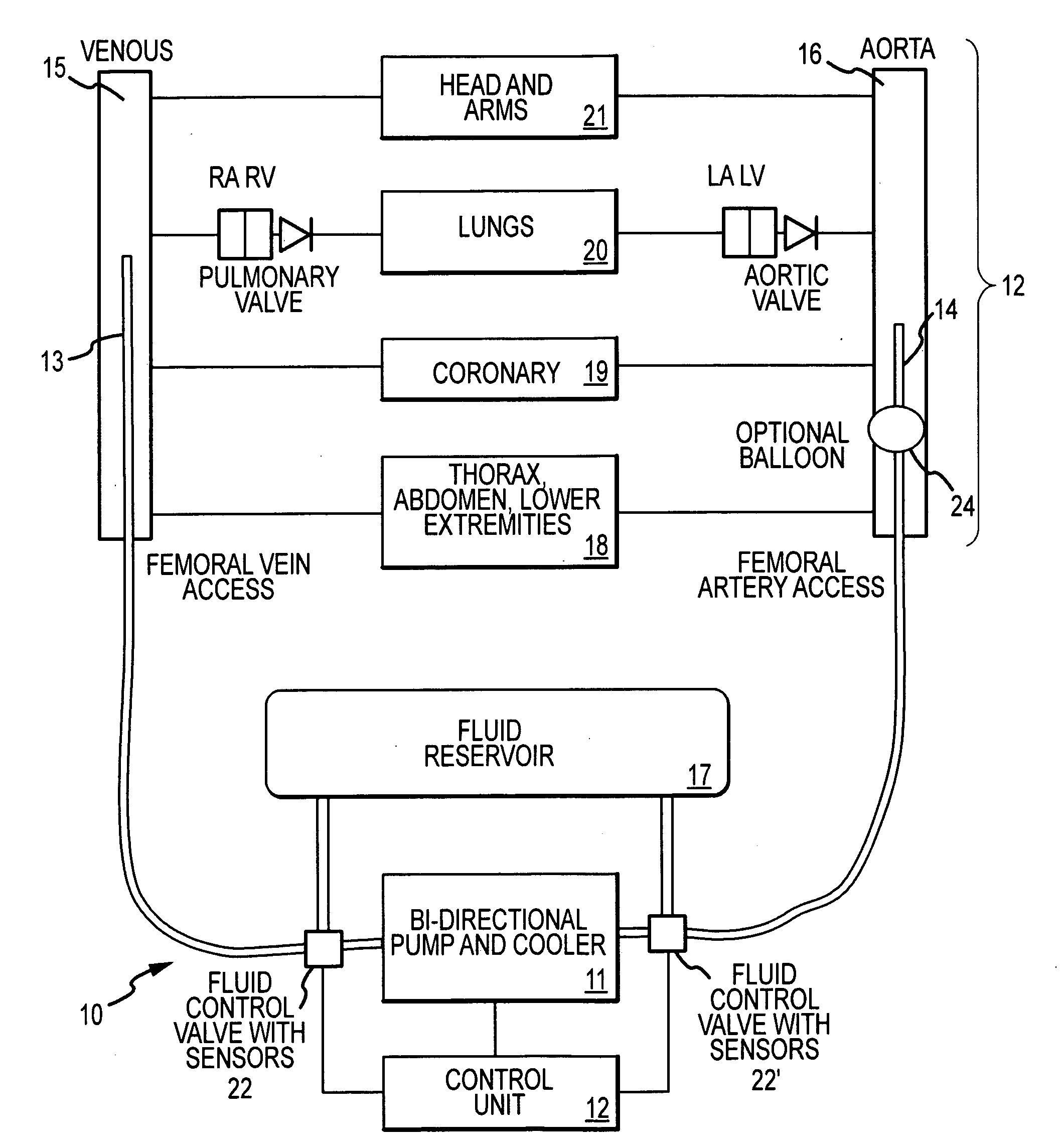
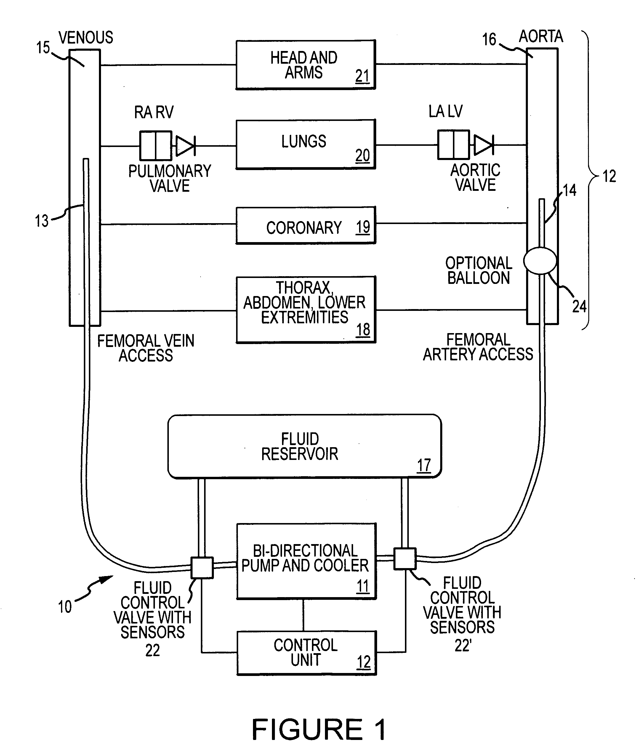
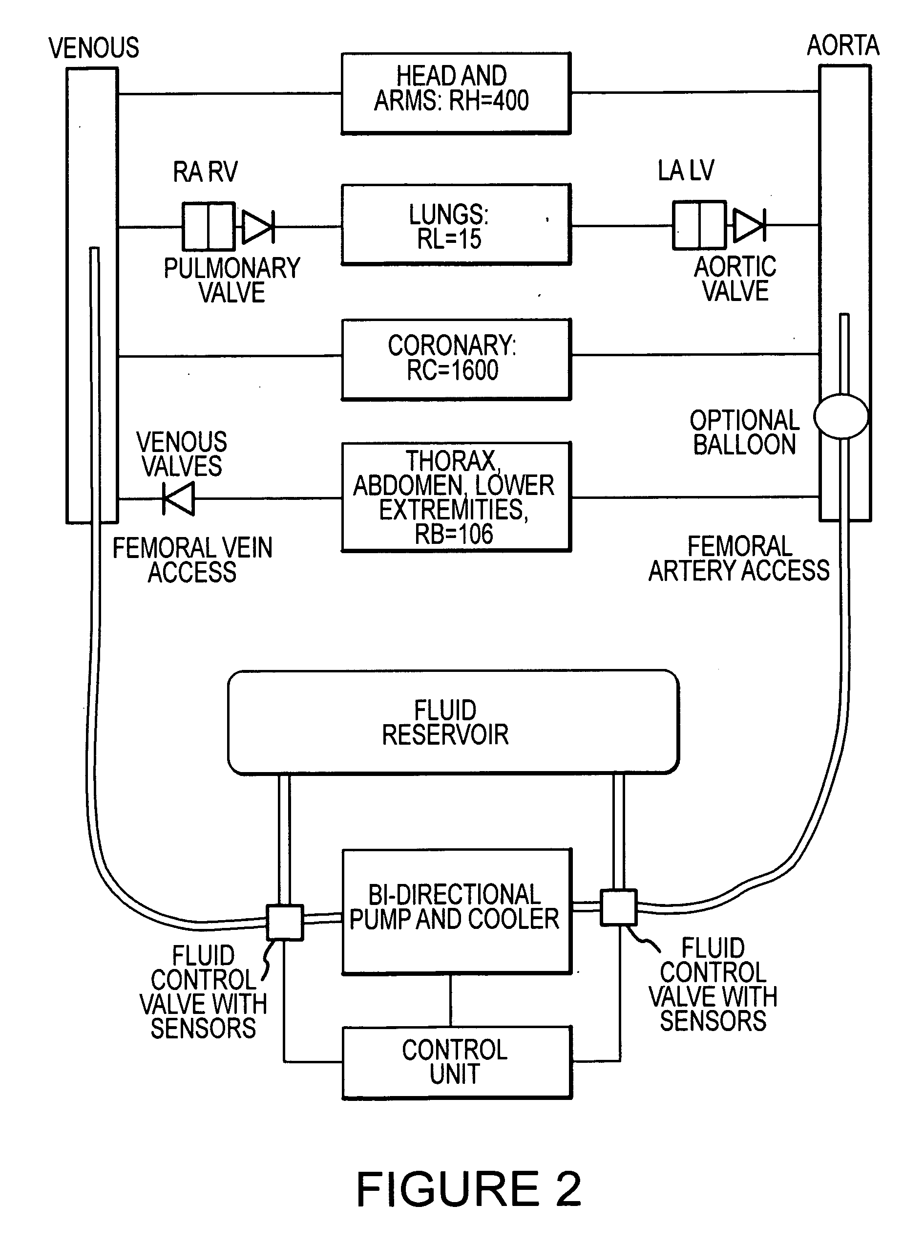
[0019]FIG. 1 illustrates a block diagram of a cardiopulmonary bypass device 10 according to an embodiment of the present invention connected to a body. The device 10 includes first 13 and second 14 tubes for connection to veins 15 and arteries 16, respectively. Elements 15 and 16 may represent ...


PUM


Abstract

A cardiopulmonary bypass device may include a first tube configured for connection to a vein and a second tube configured for connection to an artery. The device may further include a pump connected between the first and second tubes. In a first mode, the pump may pump fluid in one direction and in a second mode, the pump may pump fluid in the opposite direction. A control unit may be coupled to the pump to control its operation. Lungs may functions as the oxygenator of the cardiopulmonary bypass device.

Description

CROSS-REFERENCE TO RELATED APPLICATION(S)[0001]This application claims the benefit of United Kingdom Application No. 0709908.8, entitled “CARDIOPULMONARY BYPASS DEVICE”, filed May 23, 2007, which application is hereby incorporated by reference in its entirety.TECHNICAL FIELD[0002]This invention relates to cardiopulmonary bypass devices and methods.BACKGROUND OF THE INVENTION[0003]Despite investments in research, in training, in equipment and infrastructure, survival from unexpected cardiac arrest has been virtually unchanged over the past couple of decades. On average, the survival rate is approximately 5% in USA / Europe, but can even be as low as 2% in the bigger cities, or well above 20% in those cities with the best implementation of science and education.[0004]One factor influencing survival is time elapsed from cardiac arrest onset until professional treatment begins. This time varies a lot. It is known that the vital organs can sustain approximately 5-10 minutes without perfusi...

Claims


Application Information

Patent Timeline
IPC IPC(8): A61M1/10A61N1/362
CPCA61M1/3666A61M16/10A61M2202/0208A61M2205/3606A61M2205/366A61M2230/202A61M16/0084A61M1/3667A61M1/3623A61M1/3621A61M60/50
Inventor MYKLEBUST, HELGE
Owner LAERDAL MEDICAL AS
Learn More