
Augmented wind power generation system using continuously variable transmission and methd of operation

a continuously variable transmission and wind power technology, applied in the direction of electric generator control, machines/engines, mechanical equipment, etc., can solve the problems of increasing the size of the gear box, increasing the cost of wind power generation, and not being reliably availabl

Active Publication Date: 2008-11-20
V3 TECH
View PDF23 Cites 92 Cited by
  • Summary
  • Abstract
  • Description
  • Claims
  • Application Information

AI Technical Summary

Problems solved by technology

As a result, wind power generation has traditionally been expensive to produce and not reliably available.
Furthermore, a larger rotor assembly applies greater torque stress to a gear box, requiring that the gear box be larger in size and made of more exotic and expensive materials.
Finally, even with exotic materials and sturdier supports, a larger rotor assembly is still limited to a lower maximum wind speed at which the rotor assembly can operate without causing damage to the mechanical components of the wind tower.
Although providing benefits over a larger rotor assembly, both configurations of augmented wind power generation systems described above continue to be constrained by inefficiencies in gear box and or generator performance.
As a result, energy is lost due to the use of less than ideal generators or to a limitation of wind speed environments in which the turbine and gear box assembly can operate without causing damage to the components of the system.

Method used


Image

  • Augmented wind power generation system using continuously variable transmission and methd of operation
  • Augmented wind power generation system using continuously variable transmission and methd of operation
  • Augmented wind power generation system using continuously variable transmission and methd of operation

Examples


Embodiment Construction

[0017]FIGS. 1 through 5, discussed below, and the various embodiments used to describe the principles of the present disclosure in this patent document are by way of illustration only and should not be construed in any way to limit the scope of the disclosure. Those skilled in the art will understand that the principles of the present disclosure may be implemented in any suitably arranged augmented wind power generation system.

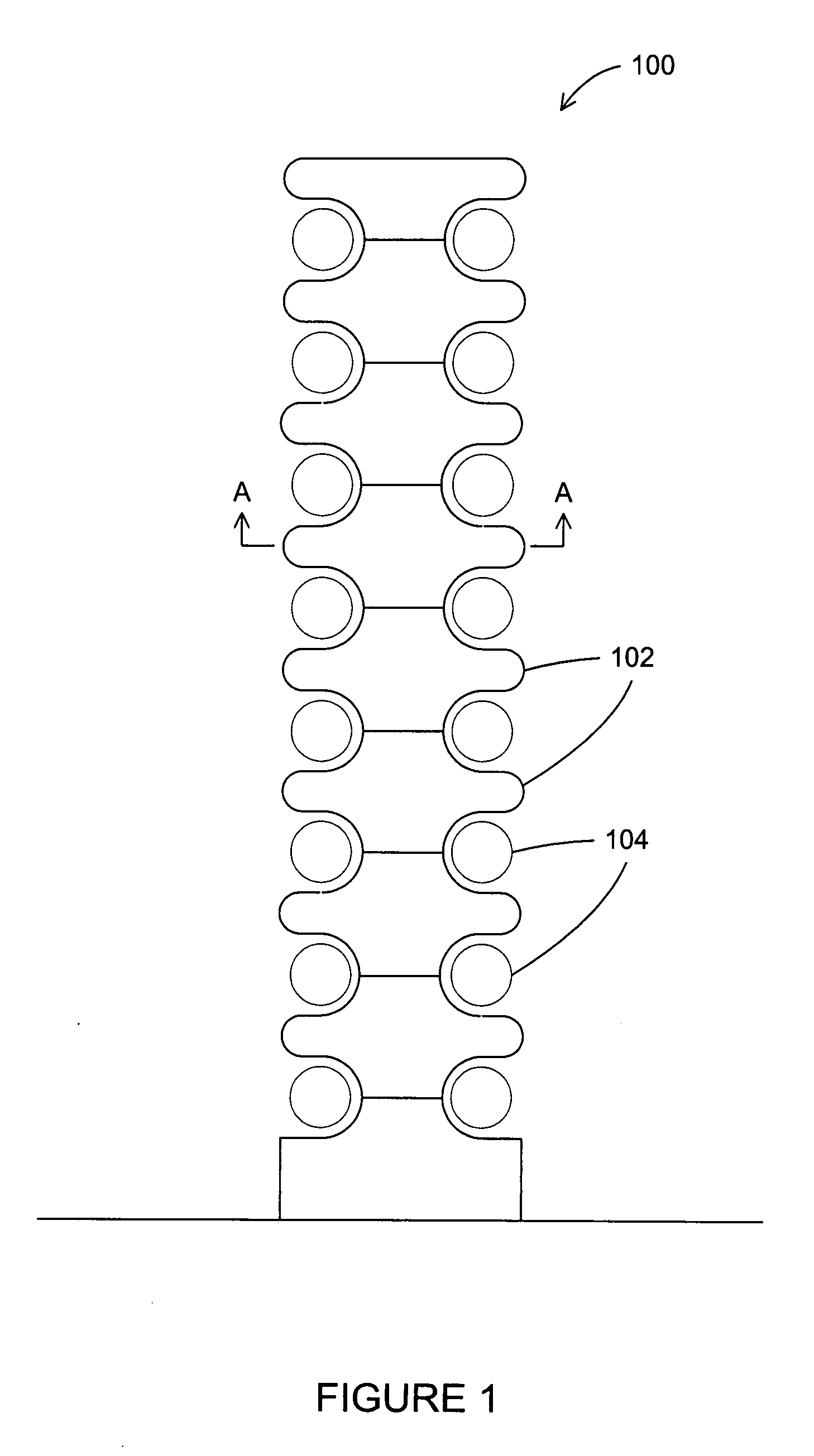
[0018]FIG. 1 illustrates an augmented wind power generation system 100 according to the disclosure. The system 100 comprises an internal central tower (not shown in FIG. 1) and a plurality of preferably stationary vertically stacked wind acceleration modules 102. The modules 102 are shaped to create semi-toroidal hollows around the tower. That is, the modules are substantially circularly symmetrical about a vertical axis, having an outer surface contour as shown in FIG. 1. The shape of modules 102 has the effect of increasing the velocity of wind flowing aroun...


PUM


Abstract

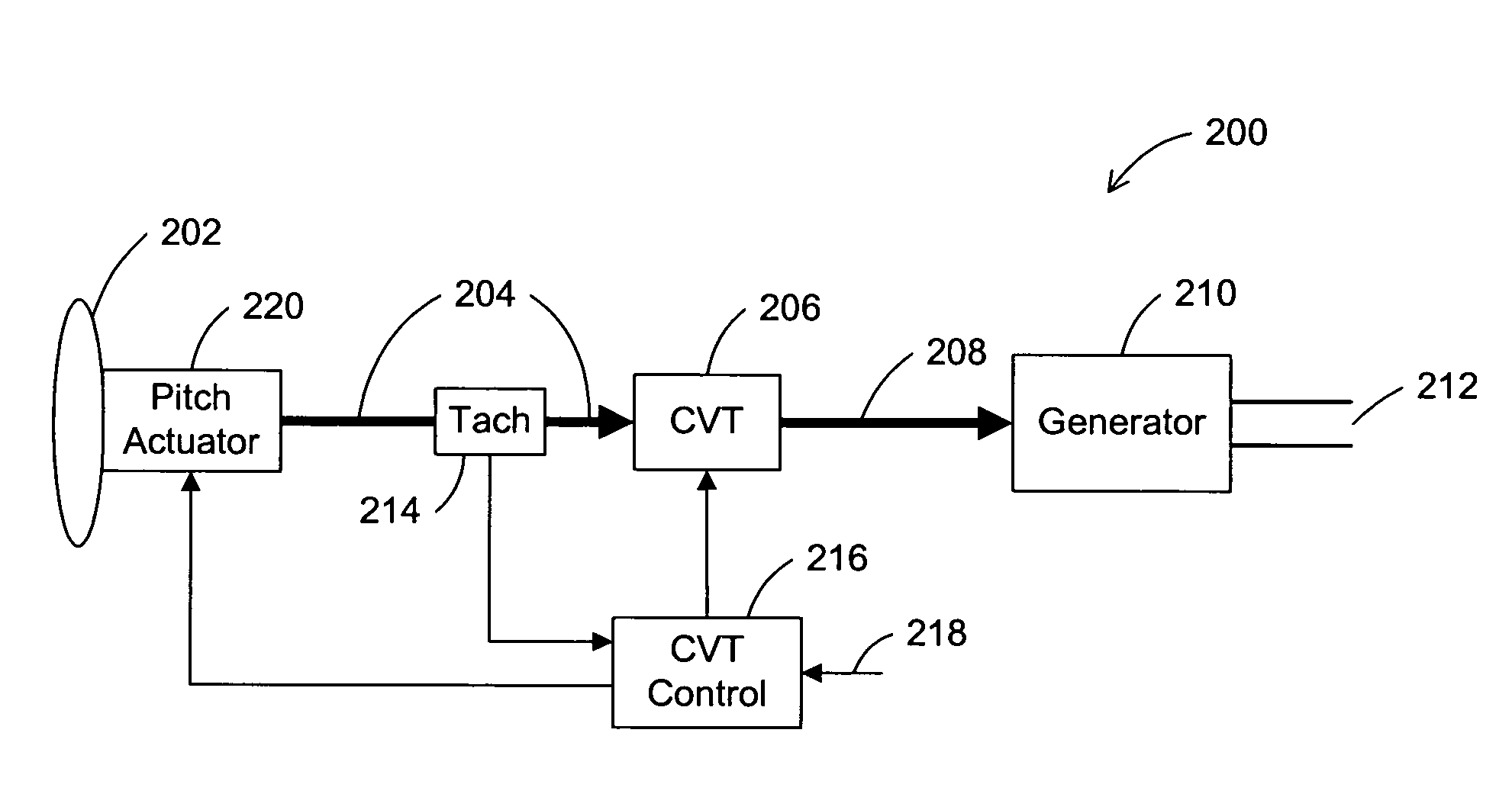
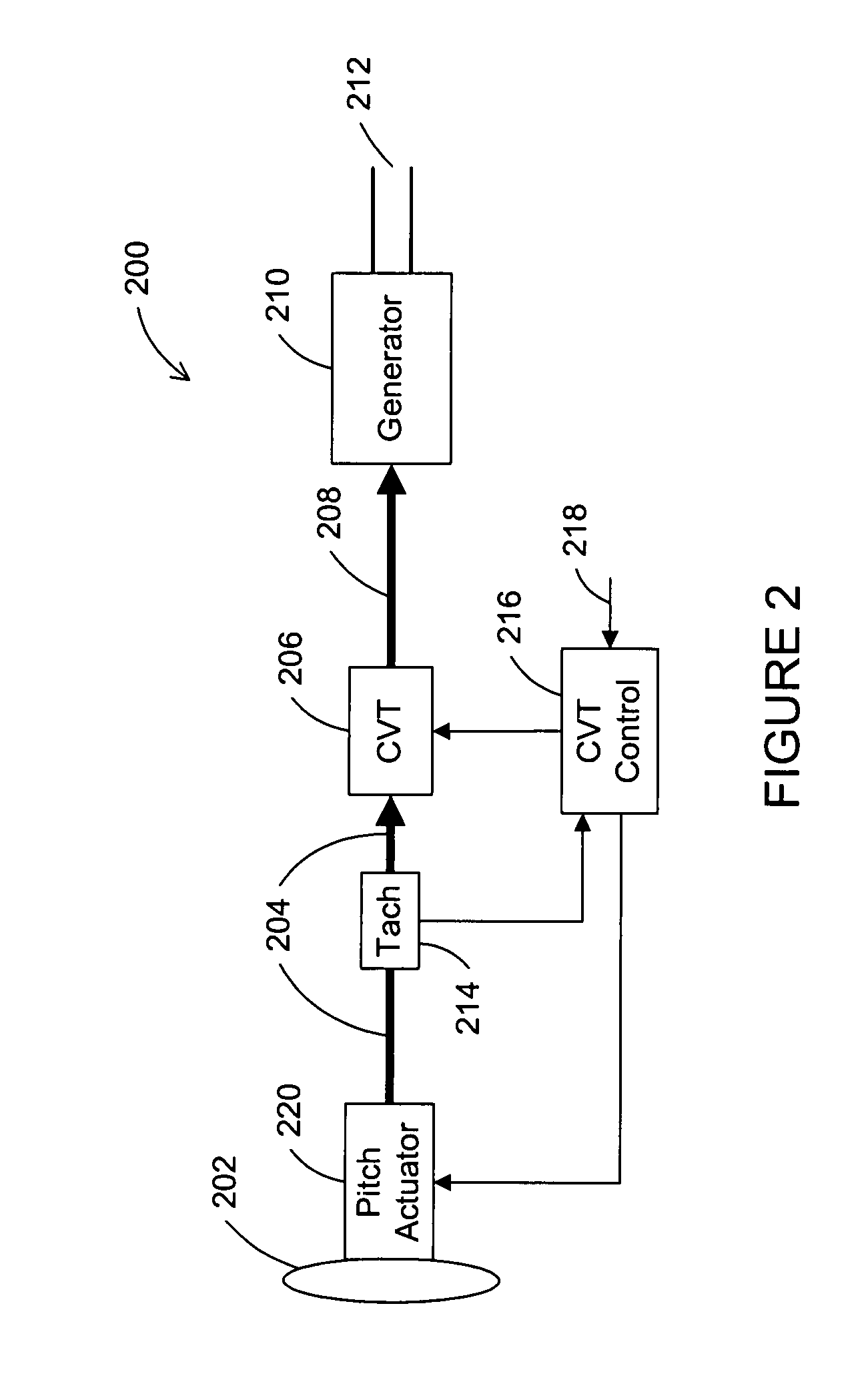
A wind power generating apparatus is provided. The apparatus includes a plurality of vertically stacked wind acceleration modules that are shaped to accelerate wind passing between them. At least one of the modules includes a rotor assembly, a continuously variable transmission (CVT) mechanically coupled to the rotor assembly, and an electrical generator mechanically coupled to the CVT. The electrical generator is capable of converting mechanical energy transferred by the CVT from the rotor assembly into electrical energy. A sensor may be mechanically coupled to the rotor assembly or the electrical generator and electrically coupled to a controller. The controller may control the CVT according to a signal received from the sensor such that the electrical generator operates within a predetermined range of rotational velocities.

Description

TECHNICAL FIELD OF THE INVENTION[0001]The present application relates generally to electrical power generation and, more specifically, to an apparatus and method for generating electrical power from wind.BACKGROUND OF THE INVENTION[0002]The environmental costs of fossil fuels and the political instabilities of oil-producing regions have intensified efforts to develop alternative energy sources that are environmentally clean and more reliable. Wind-driven power generation systems are of particular interest. Wind power may be converted to electrical power using a rotor assembly, either horizontally or vertically oriented. The rotor blades convert the energy of the moving air into a rotational motion of a drive shaft. An electrical generator coupled to the drive shaft then converts the rotational motion into electrical power. Typically, a fixed-ratio gear box converts the low rotation speed of the rotor assembly to a higher rotation speed for the electrical generator.[0003]A convention...

Claims


Application Information

Patent Timeline
IPC IPC(8): F03D9/00H02P9/04
CPCF03D11/02F05B2220/706H02P2101/15Y02E10/722Y02E10/725H02P9/06F03D9/25F03D15/00Y02E10/72
Inventor CORY, KENNETH D.
Owner V3 TECH
Learn More