
Laryngeal Mask Adapted For the Introduction and Removal of an Intubation Probe

a technology of intubation probe and laryngeal mask, which is applied in the direction of respirator, trachea tube, etc., can solve the problems of masks that are not suitable for emergency intubation conditions, masks that are difficult to move or dislodge, and are therefore difficult to operate intubation operations. and time-consuming,

Inactive Publication Date: 2008-11-13
BASSOUL BRUNO
View PDF7 Cites 30 Cited by
  • Summary
  • Abstract
  • Description
  • Claims
  • Application Information

AI Technical Summary

Benefits of technology

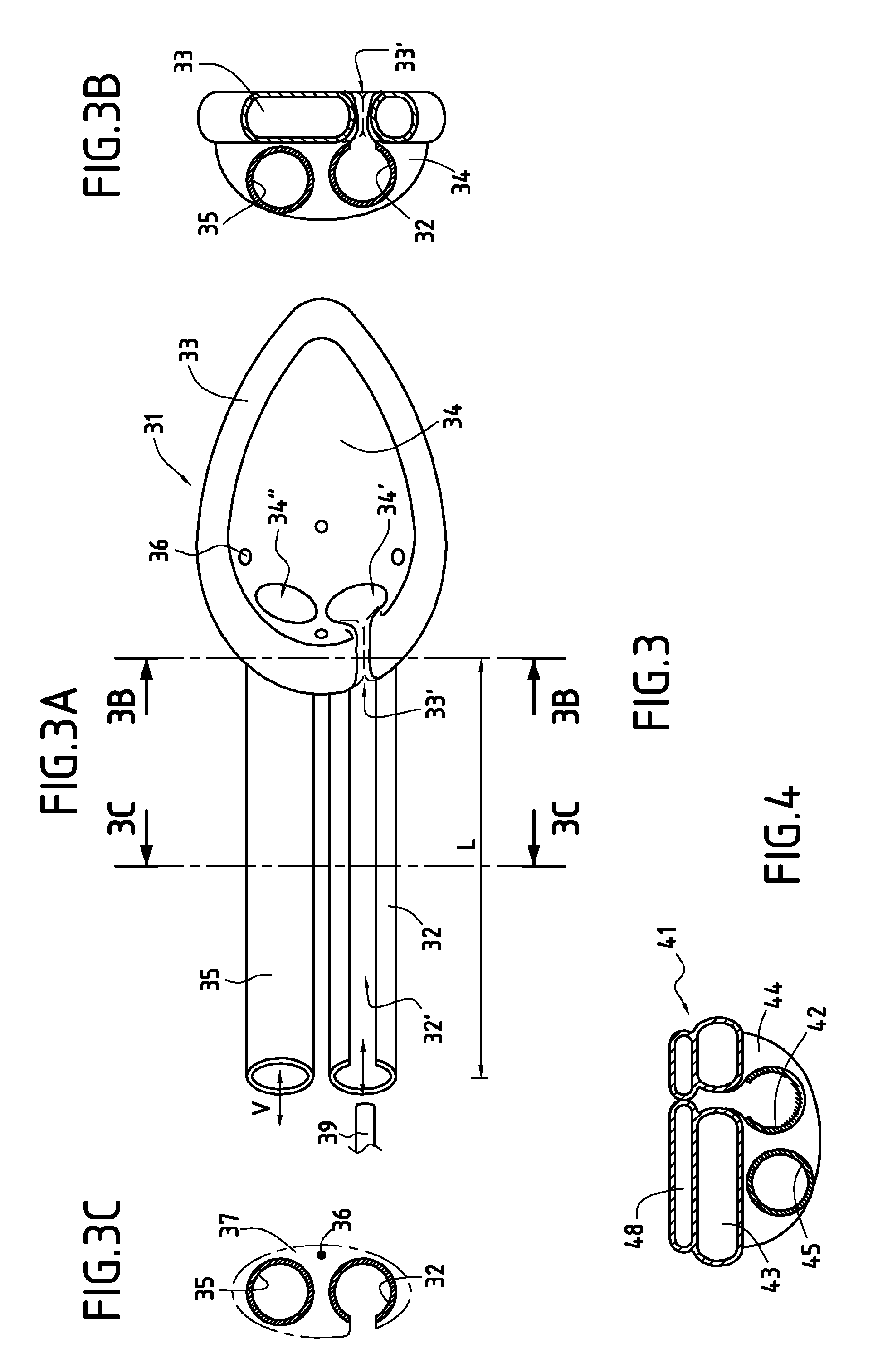
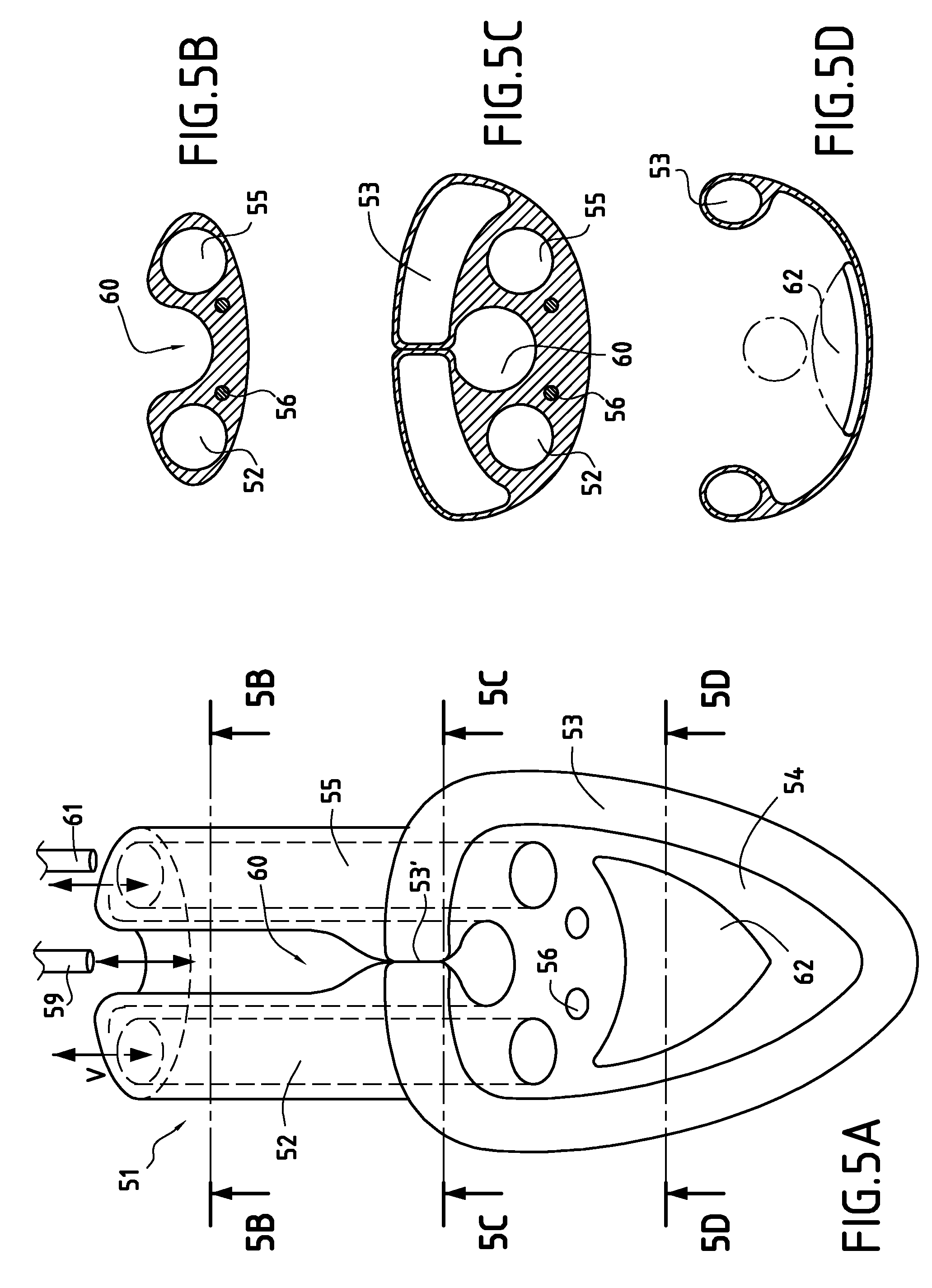
[0009]A main object of the present invention is to mitigate such drawbacks by proposing a laryngeal mask designed to be introduced level with a patient's larynx, the mask comprising at least one tubular structure designed to open out level with the patient's vocal chords, enabling a mandrel and / or an intubation probe to be introduced, and including means for releasing the mandrel or the intubation probe, these release means being such that the tubular structure is open over at least a fraction of its length so as to allow the mandrel or the intubation probe to be released after it has been introduced therein.
[0010]Such a mask makes it possible to envisage easy intubation in an emergency situation, in particular for the purpose of installing artificial ventilation.
[0011]The laryngeal mask of the invention is easy to put into place and it makes it easy to slide in an intubation probe. The practitioner can press against the tubular structure that rests against the posterior portion of the oropharynx in order to slide in the intubation probe or the mandrel along which the tubular intubation probe is to be slid. The laryngeal mask provides a kind of chute that serves to guide the probe towards the patient's trachea.

Problems solved by technology

The intubation operation is thus often difficult and time-consuming.
Such masks are therefore ill-suited to emergency intubation conditions, where it is necessary to act quickly and effectively.
In addition, when it is desired to remove a laryngeal mask after the intubation probe or a mandrel has been put into place, it has been found that there exists a considerable danger of moving the probe or the mandrel detrimentally or even of dislodging it, with this happening when the sealing pad is deflated.

Method used


Image

  • Laryngeal Mask Adapted For the Introduction and Removal of an Intubation Probe
  • Laryngeal Mask Adapted For the Introduction and Removal of an Intubation Probe
  • Laryngeal Mask Adapted For the Introduction and Removal of an Intubation Probe

Examples


first embodiment

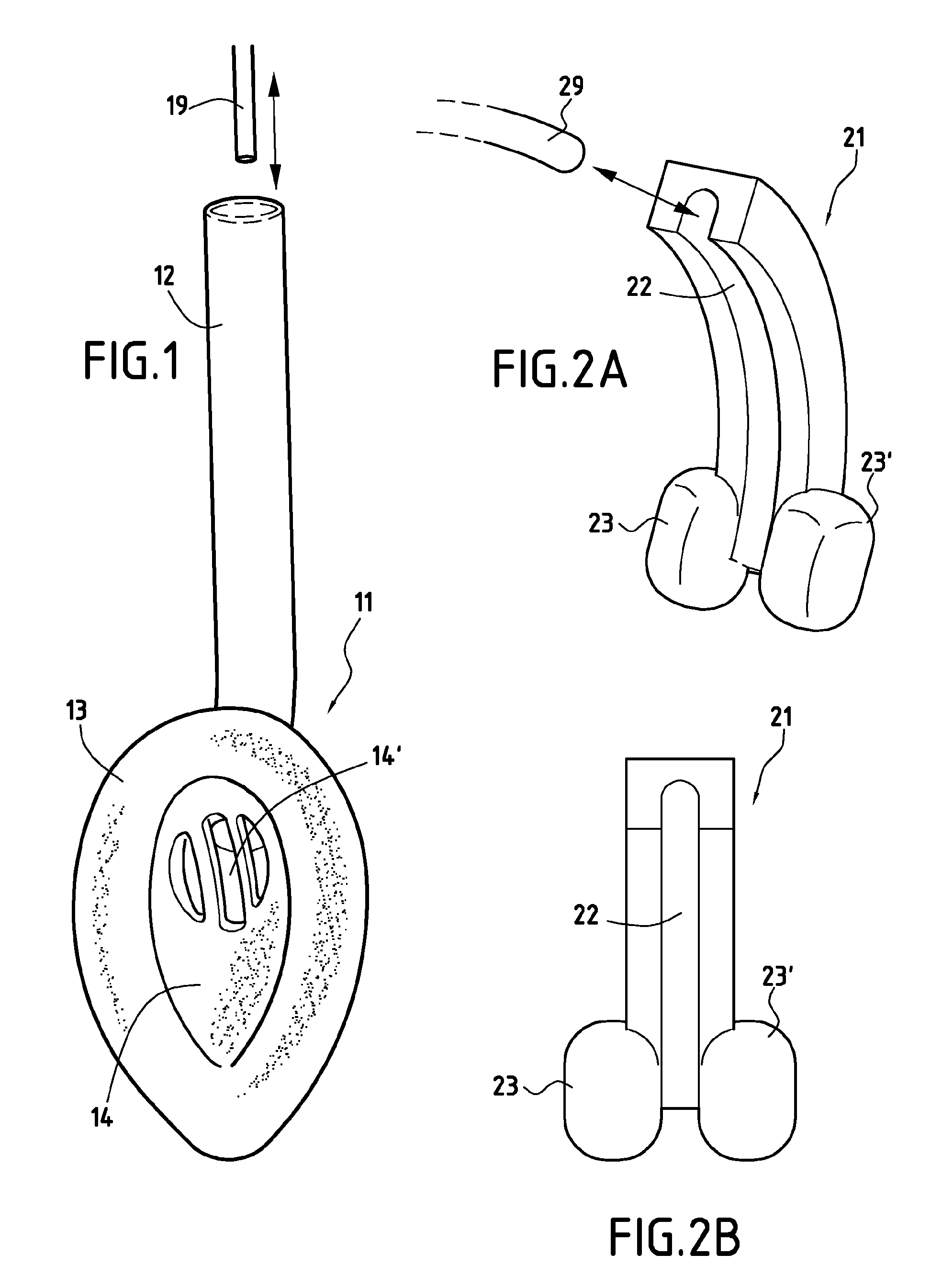
[0038]FIGS. 2A and 2B show a laryngeal mask 21 constituting the invention.

[0039]The laryngeal mask 21 comprises a tubular structure 22 that is open along its entire length.

[0040]The tubular structure 22 is structurally such that it is substantially in the form of a kind of chute making it possible, by sliding, to introduce: an intubation probe 29, optionally engaged on a long mandrel extending beyond the tubular structure 22; a mandrel; or a conventional fibroscope. A long mandrel is typically a guide mandrel having a length of 40 centimeters (cm) or more.

[0041]In the example shown, the tubular structure 22 is provided with two pads 23 and 23′ referred to as “disengagement” pads that are placed on either side of the tubular structure 22.

[0042]The function of these pads 23 and 23′ is to be introduced under the patient's tongue mass and to be inflated in order to lift the tongue mass and clear a view towards the vocal chords. This characteristic is particularly advantageous when the p...


PUM


Abstract

The invention relates to a laryngeal mask for being introduced level with a patient's larynx and including at least one tubular structure designed to open out level with the patient's vocal chords to enable a mandrel and / or an intubation probe to be introduced, and including means for releasing the mandrel or the intubation probe, these release means being such that the tubular structure is open over at least a fraction of its length so as to allow the mandrel or the intubation probe to be released after it has been introduced therein.

Description

BACKGROUND OF THE INVENTION [0001]The present invention relates to the general field of devices used in anesthesia, intensive care, and medical emergencies. More precisely, the invention relates to laryngeal masks.[0002]Such laryngeal masks are used for managing airways, in particular during anesthesia.[0003]A first known type of mask 11 is shown diagrammatically in FIG. 1. It comprises a tubular structure 12 and at least one inflatable sealing pad 13 connected to the end of the tubular structure 12. When this end is introduced level with a patient's larynx, the sealing pad 13 is placed at the entrance to the patient's trachea level with the vocal chords to provide sealing by inflating the pad 13. In the example shown in FIG. 1, the inflatable sealing pad 13 is in the form of an egg-shaped collar and is connected to a sheet 14. The tubular structure 12 opens out to an orifice 14′ in the sheet 14.[0004]In other embodiments of laryngeal masks for performing the same functions, the sea...

Claims


Application Information

Patent Timeline
Patent Type & Authority Applications(United States)
IPC IPC(8): A61M16/00
CPCA61M16/04A61M16/0463A61M16/0409A61M16/0415A61M16/0431A61M16/1055A61M16/106A61M16/0486
Inventor BASSOUL, BRUNO
Owner BASSOUL BRUNO
Learn More