
Differential Torque Operation for Internal Combustion Engine

Inactive Publication Date: 2008-11-13
FORD GLOBAL TECH LLC
View PDF14 Cites 30 Cited by
  • Summary
  • Abstract
  • Description
  • Claims
  • Application Information

AI Technical Summary

Benefits of technology

[0001]Various control strategies have been employed to improve fuel efficiency of an internal combustion engine. As one example, engines have been operated in what may be referred to as variable displacement operation or partial cylinder mode, whereby combustion in one or more cylinders of the engine is temporarily discontinued or deactivated when operating at partial load. In this way, the engine may be operated with a lower number of firing cylinders, thereby improving fuel efficiency under these partial load conditions.
[0005]In this way, the inventors of the present disclosure have recognized that fuel efficiency may be increased while also reducing NVH even during conditions where engine cylinders are not deactivated by increasing the torque differential between at least two groups of firing cylinders with increasing engine speed. Note that in some examples, the torque differential between two groups of cylinders may be adjusted by adjusting airflow to at least one group of cylinders without necessarily adjusting the amount of fuel delivered to the cylinders. Also, note that the alternating firing of the cylinder may be non-consecutive, or may be consecutive. Further note that while in some examples achieve advantageous operation without fuel differentiation, in other examples fuel differentiation may be used.

Problems solved by technology

However, when some of the engine cylinders are deactivated to improve fuel efficiency, the noise and vibration harshness (NVH) may increase.
Furthermore, the above approach relies solely on fuel differentiation to counteract for the deactivation of one or more of the engine cylinders, which may result in reduced vibration at the cost of reduced fuel efficiency, under some conditions.

Method used


Image

  • Differential Torque Operation for Internal Combustion Engine
  • Differential Torque Operation for Internal Combustion Engine
  • Differential Torque Operation for Internal Combustion Engine

Examples


Embodiment Construction

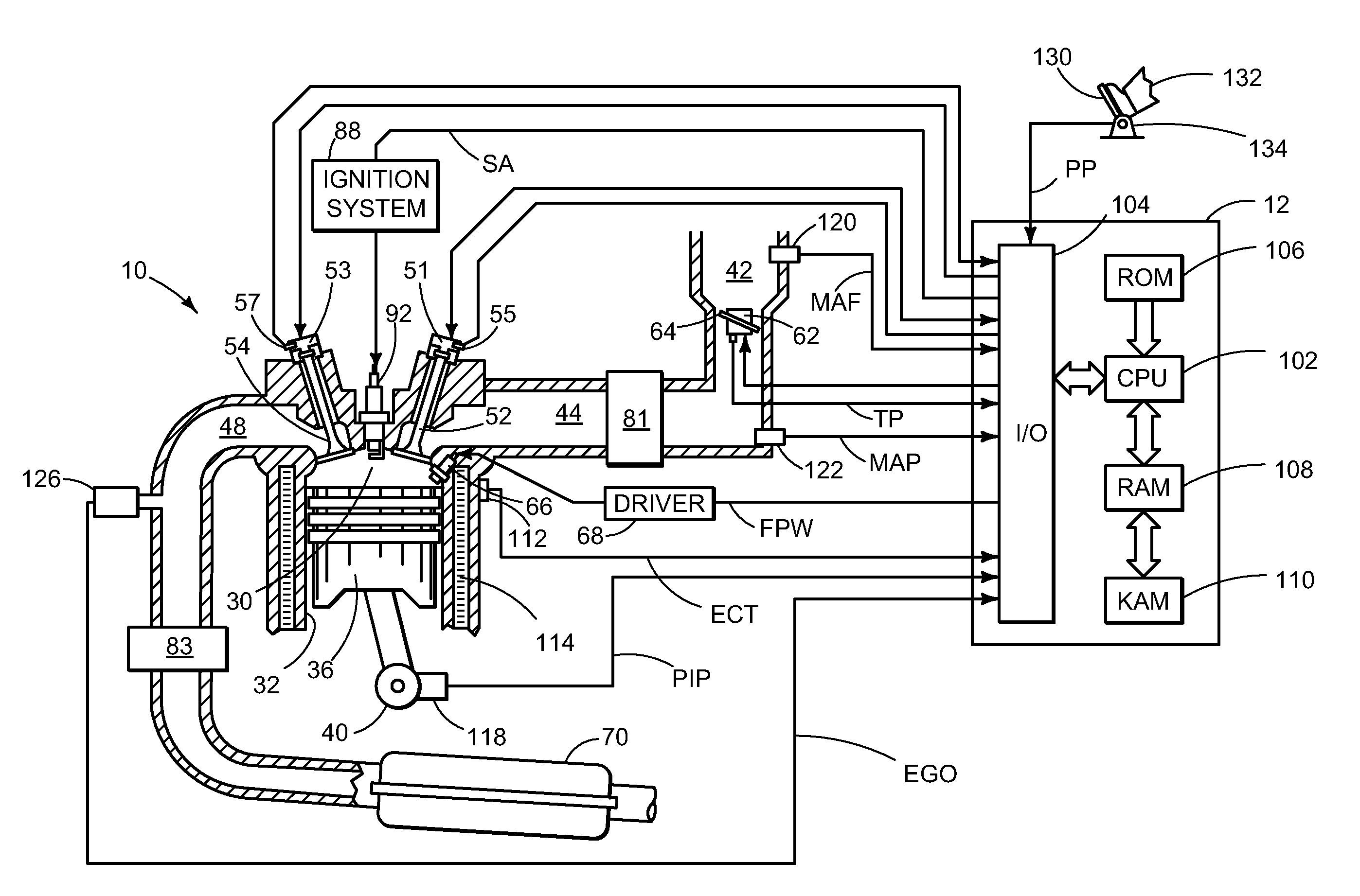
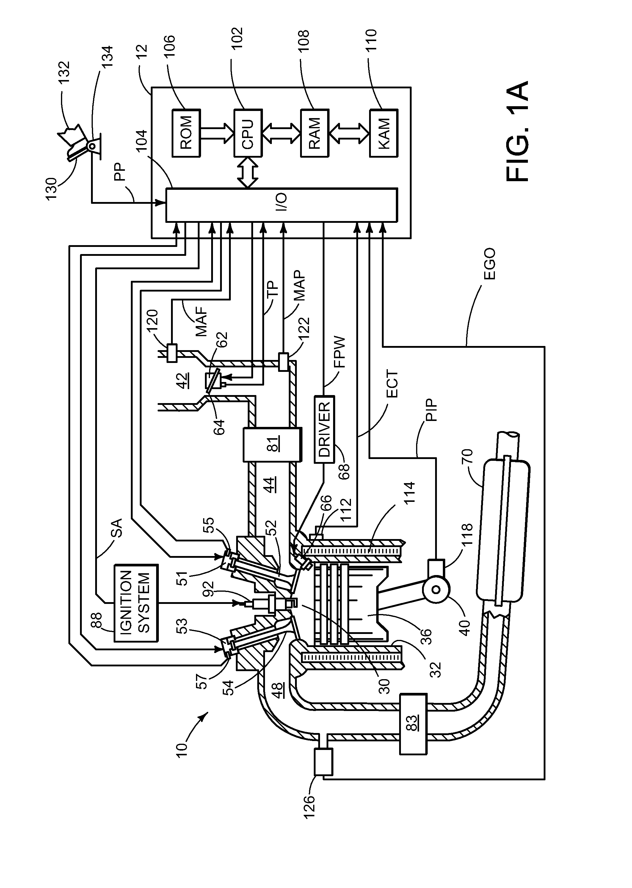
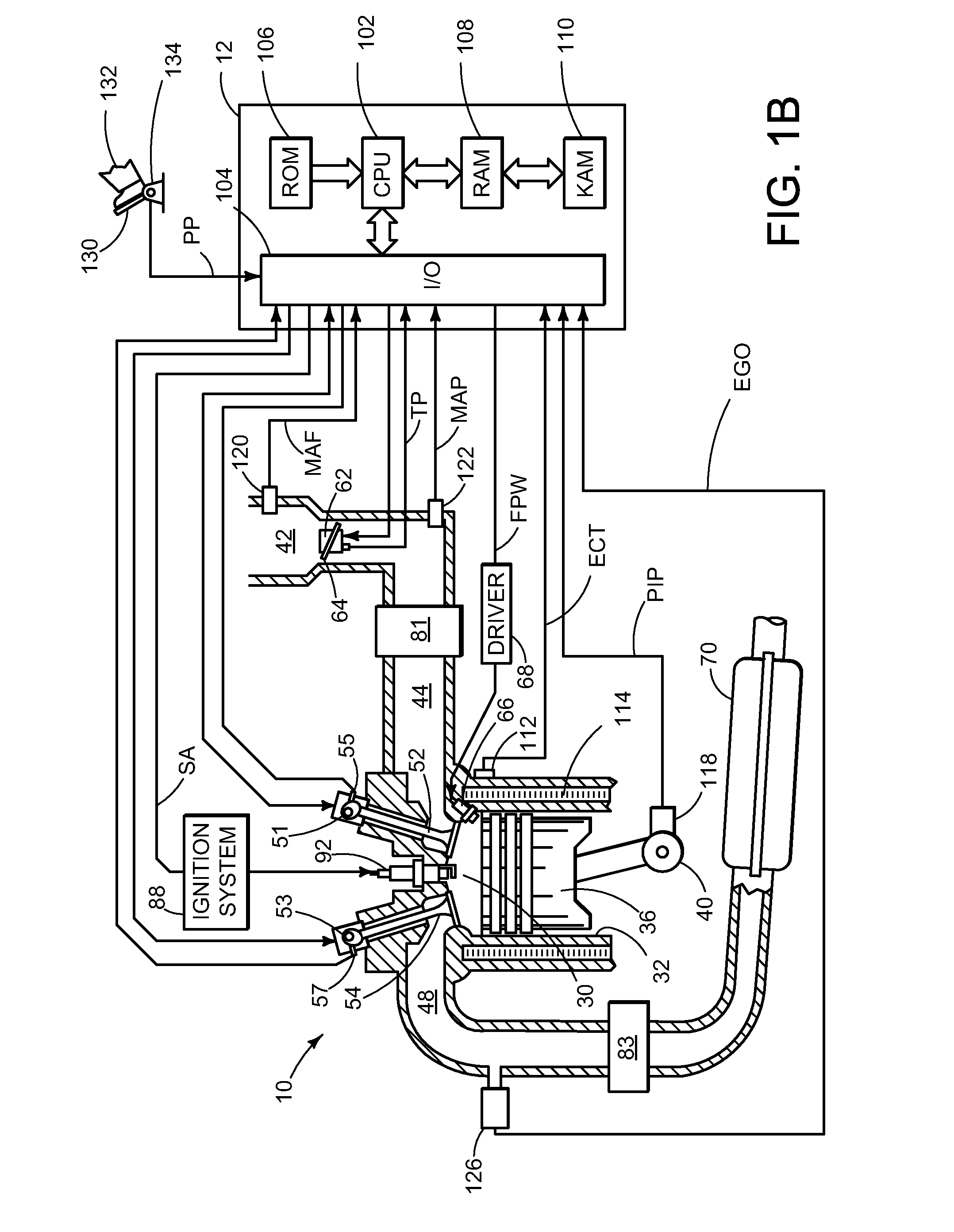
[0019]An approach for varying a torque differential between at least two groups of cylinders of an internal combustion engine in response to at least an operating condition of the engine will be described herein in greater detail. Referring now to FIGS. 1 and 2, various engine configurations will be described, which may be used with the various control strategies described herein. In particular, FIGS. 1A, 1B, and 1C illustrate example cylinders of a multi-cylinder internal combustion engine while FIG. 1D illustrates an example engine including a boosting device. FIGS. 2A, 2B, and 2C illustrate example engines having multiple cylinders.

[0020]Engine 10, which may be represented by the various engine configurations illustrated by FIGS. 1 and 2, among others, may be controlled at least partially by a control system including at least a controller 12. An example cylinder or combustion chamber 30 of engine 10 may include combustion chamber walls 32 with moveable piston 36 positioned there...


PUM


Abstract

A method of operating an internal combustion engine having a plurality of cylinders including at least a first cylinder and a second cylinder, the method comprising firing the first cylinder and the second cylinder in an alternating sequence; during a first mode, adjusting an operating parameter of the engine to produce a first difference between an amount of torque produced by the firing of the first cylinder and an amount of torque produced by the firing of the second cylinder; during a second mode, adjusting the operating parameter of the engine to produce a second difference between an amount of torque produced by the firing of the first cylinder and an amount of torque produced by the firing of the second cylinder; and performing the first mode at a higher engine speed than the second mode; wherein the first difference is greater than the second difference.

Description

BACKGROUND AND SUMMARY[0001]Various control strategies have been employed to improve fuel efficiency of an internal combustion engine. As one example, engines have been operated in what may be referred to as variable displacement operation or partial cylinder mode, whereby combustion in one or more cylinders of the engine is temporarily discontinued or deactivated when operating at partial load. In this way, the engine may be operated with a lower number of firing cylinders, thereby improving fuel efficiency under these partial load conditions.[0002]However, when some of the engine cylinders are deactivated to improve fuel efficiency, the noise and vibration harshness (NVH) may increase. The increase in NVH may be caused by the reduction in positive torque from the deactivated cylinders. In one approach as set forth, for example, by U.S. Pat. No. 6,247,449, the change in torque may be counteracted by changing the amount of torque produced by the remaining firing cylinders by differe...

Claims


Application Information

Patent Timeline
IPC IPC(8): F02D41/00B60L50/16
CPCF02B1/12F02D41/0002F02D41/0007F02D41/0082F02D41/0085F02D41/1461F02D41/3029F02D2200/0404F02D2250/28F02P5/1522Y02T10/46Y02T10/40
Inventor SURNILLA, GOPICHANDRABERGER, AL HENRYCHEN, WAN JOEHOUSE, CHRISTOPHER
Owner FORD GLOBAL TECH LLC
Learn More