Image-Correction Method and Image Pickup Apparatus
a pickup apparatus and image technology, applied in the field of image correction technology, can solve the problems of deterioration in performance such as the decrease of the frame rate for picking up images, the inability of the n-order function to implement the inability to achieve the shading correction with sufficient accuracy, so as to achieve the effect of not deteriorating performan
- Summary
- Abstract
- Description
- Claims
- Application Information
AI Technical Summary
Benefits of technology
Problems solved by technology
Method used
Image

Examples
embodiment 1
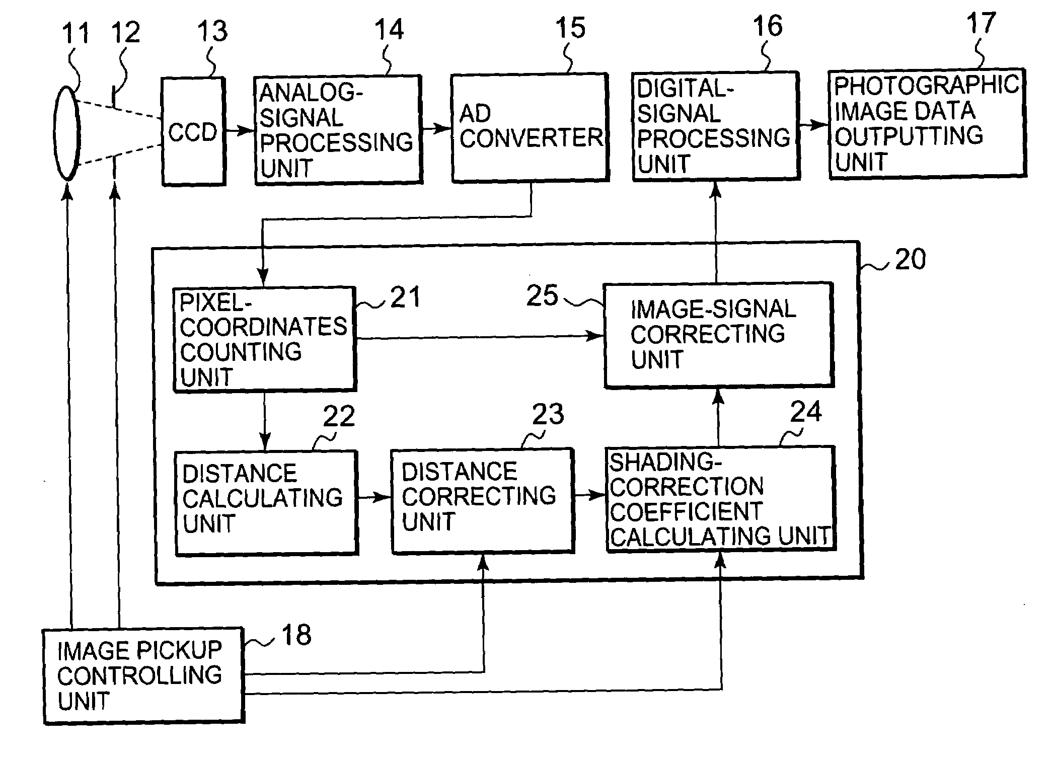
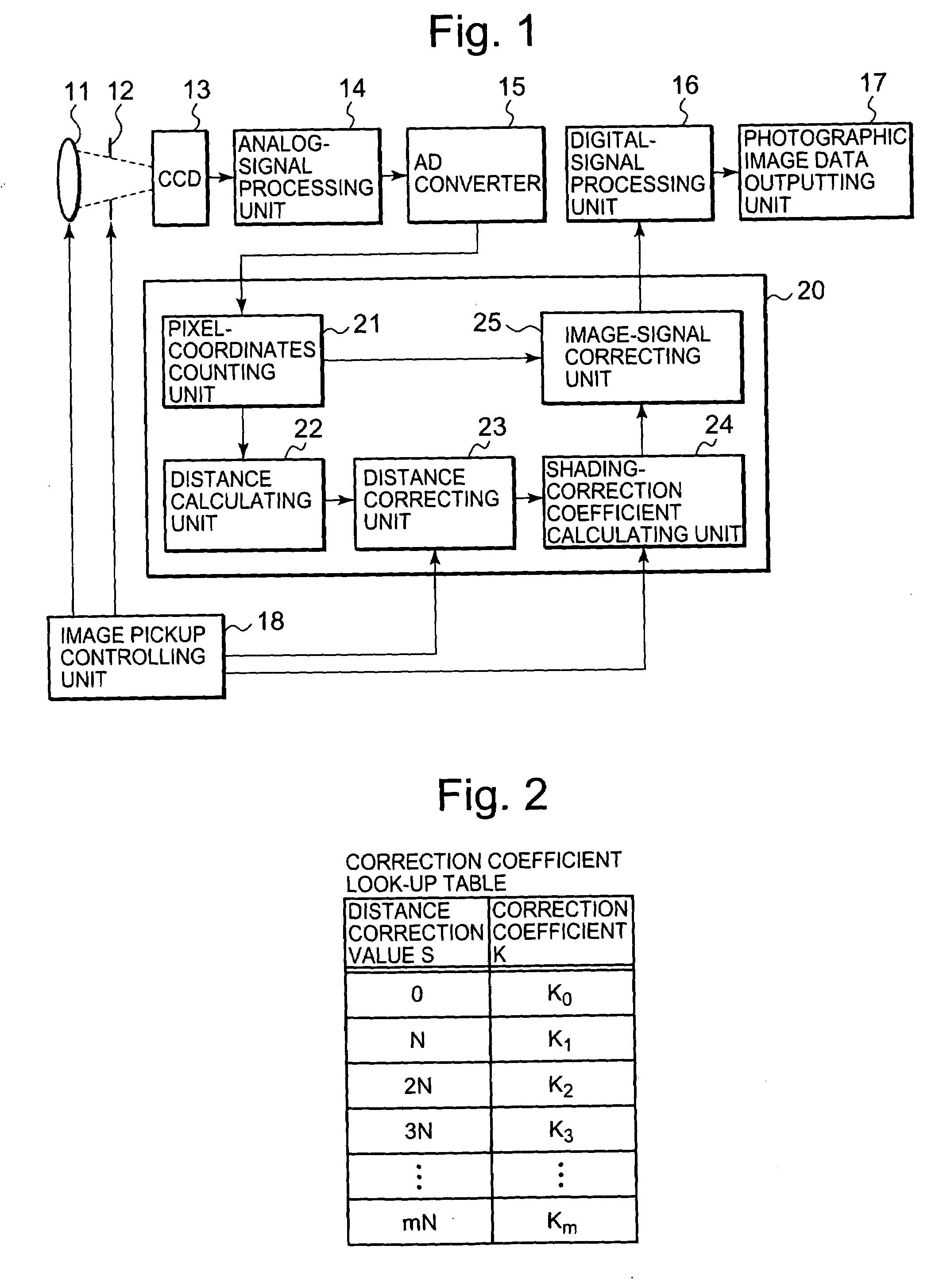
[0021]FIG. 1 is a block diagram for illustrating an image pickup apparatus according to Embodiment 1 of the present invention.
[0022]In FIG. 1, the image pickup apparatus is made up of an image pickup lens 11 having an optical zooming function, a diaphragm mechanism 12 for adjusting the amount of incident light to a camera, a CCD (Charge Coupled Device) 13 that is a photoelectric transducer, an analog-signal processing unit 14, an analog / digital converter (AD converter) 15, a digital-signal processing unit 16, an photographic image data outputting unit 17 for storing a photographic image data in a storage area, and an image pickup controlling unit 18 for controlling the optical zooming function and the diaphragm mechanism, and for changing settings for a distance correcting unit 23 and a shading-correction coefficient calculating unit 24, in a shading-correction processing section 20 described later.
[0023]Moreover, the shading-correction processing section 20 for implementing shading...
embodiment 2
[0050]In Embodiment 1 described above, a configuration is disclosed, in which shading correction is applied in the same way to all pixels, without considering color components of a pixel. However, in some cases, due to the properties of a micro lens for focusing a light beam to each pixel of a solid-state image pickup device and the like, shading whose respective properties for each color component differ can be observed. A configuration, in the case where, in order to address these cases, different shading correction is applied to each color component, will be described below.
[0051]FIG. 4 is a block diagram for illustrating an image pickup apparatus according to Embodiment 2 of the present invention. The same reference marks in FIG. 4 indicate the same or equivalent constituent elements.
[0052]In FIG. 4, the image pickup apparatus is made up of an image pickup lens 11 having an optical zooming function, a diaphragm mechanism 12 for adjusting the amount of incident light to a camera,...
embodiment 3
[0068]In Embodiments 1 and 2, the distance between a reference point and a pixel position is obtained, and then a correction coefficient is calculated, based on the distance value. However, the calculation of a distance includes a second-order calculation and a square-root calculation, with regard to a pixel position; therefore, a relatively large calculation circuitry is required. A configuration, for reducing the amount of calculation required to implement shading correction and for implementing shading correction with a less amount of calculation, will be described below.
[0069]FIG. 6 is a block diagram for illustrating an image pickup apparatus according to Embodiment 3 of the present invention. In FIG. 6, the same reference marks indicate the same or equivalent constituent elements.
[0070]In FIG. 6, the image pickup apparatus is made up of an image pickup lens 11 having an optical zooming function, a diaphragm mechanism 12 for adjusting the amount of incident light to a camera, a...
PUM
 Abstract
Description
Claims
Application Information
 - R&D
- Intellectual Property
- Life Sciences
- Materials
- Tech Scout
- Unparalleled Data Quality
- Higher Quality Content
- 60% Fewer Hallucinations
Browse by: Latest US Patents, China's latest patents, Technical Efficacy Thesaurus, Application Domain, Technology Topic, Popular Technical Reports.
© 2025 PatSnap. All rights reserved.Legal|Privacy policy|Modern Slavery Act Transparency Statement|Sitemap|About US| Contact US: help@patsnap.com