
Brachytherapy Device Having an Alignment and Seal Adaptor

a technology of aligning and sealing adaptors, applied in radiation therapy, x-ray/gamma-ray/particle irradiation therapy, radiation therapy, etc., can solve the problems of preventing the insertion of radioactive materials into the interior channels of the tubes and/or its removal

Inactive Publication Date: 2008-10-30
NORTH AMERICAN SCI
View PDF11 Cites 15 Cited by
  • Summary
  • Abstract
  • Description
  • Claims
  • Application Information

AI Technical Summary

Benefits of technology

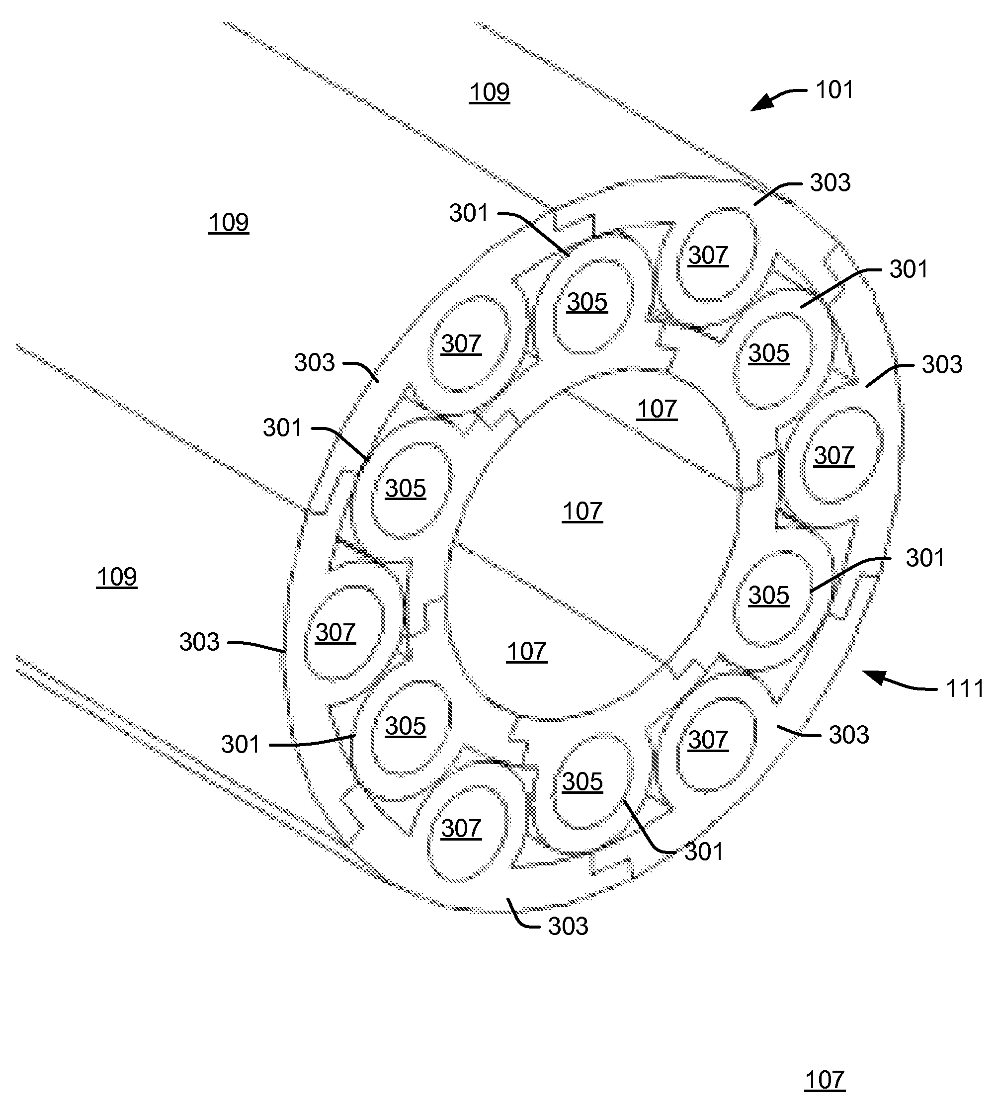
[0008]A brachytherapy device for treating tissue within a cavity of a body may include a first set of tubes configured to be inserted into the cavity through an opening at the surface of the body. Each of the tubes may have an external end and an interior channel beginning at the external end that is configured to receive radioactive material, the external ends of the tubes being bundled together. The tubes may be of a length that causes the external ends to be near the opening in the surface of the body while the tubes are in the cavity. A seal may be configured to prevent fluid that originates from the cavity from entering into the external ends of the tubes while they are near the opening in the surface of the body.
[0027]A seal may be provided for a brachytherapy device that has tubes configured to be inserted into a cavity through an opening at a surface of a body. The seal may include a substantially flat gasket that is configured to be pressed against the external ends of the tubes. The gasket may have a plurality of openings oriented so as to be aligned with the channels in the tubes when pressed against the external ends of the tubes so as to allow radioactive material to be inserted into the channels of the tubes, while preventing fluid that originates from the cavity from entering into the external ends of the tubes.

Problems solved by technology

This may impede the insertion of radioactive material into the interior channels of the tubes and / or its removal.

Method used


Image

  • Brachytherapy Device Having an Alignment and Seal Adaptor
  • Brachytherapy Device Having an Alignment and Seal Adaptor
  • Brachytherapy Device Having an Alignment and Seal Adaptor

Examples


Embodiment Construction

[0037]Illustrative embodiments are now discussed. Other embodiments may be used in addition or instead. Details that may be apparent or unnecessary may be omitted to save space or for a more effective presentation.

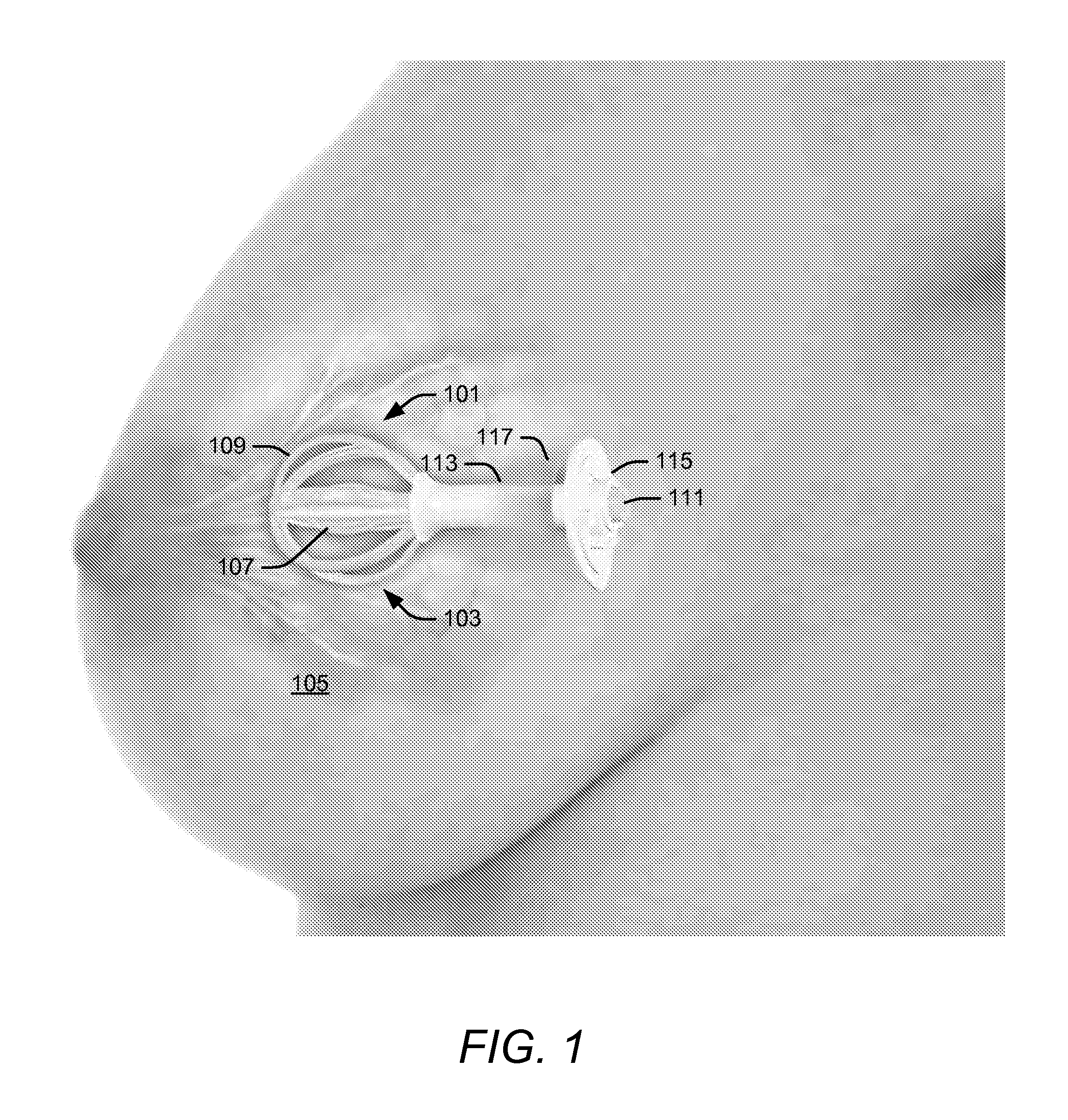
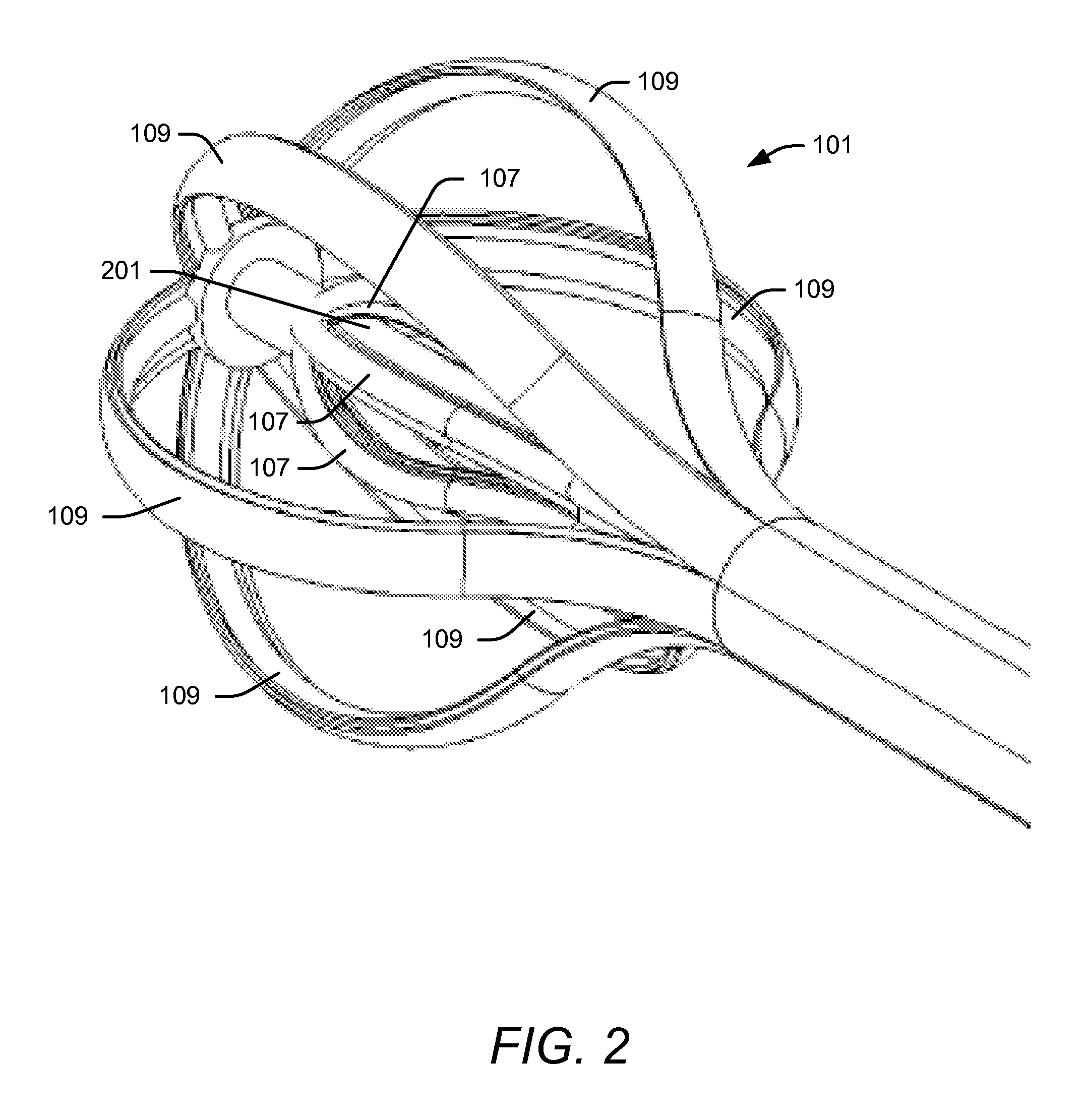
[0038]FIG. 1 illustrates a brachytherapy device after being inserted into a breast and being expanded. As shown in FIG. 1, a brachytherapy device 101 may be inserted into a cavity 103 in a breast 105. The brachytherapy device 101 may include a set of expanded inner tubes 107 and a set of expanded outer tubes 109. The inner tubes 107 and the outer tubes 109 may have external ends 111 that are bundled together. A sleeve 113 may be used to bundle the external ends 111 together. A clamp 115 may be used in addition or instead to bundle the external ends 111 together. The clamp 115 may or may not be integral with the sleeve 113.

[0039]The length of the inner tubes 107 and the outer tubes 109 may be such as to cause the external ends 111 to be near a surface 117 of the breast 105,...


PUM


Abstract

A brachytherapy device for treating tissue within a cavity of a body. The device may include a first set of tubes configured to be inserted into the cavity through an opening at the surface of the body. Each of the tubes may have an external end and an interior channel beginning at the external end that is configured to receive radioactive material. The external ends of the tubes may be bundled together. The tubes may be of a length that causes the external ends to be near the opening in the surface of the body while the tubes are in the cavity. A seal may be configured to prevent fluid that originates from the cavity from entering into the external ends of the tubes while they are near the opening in the surface of the body. The seal may include a gasket that is pressed against the external ends of the tubes. The gasket may have openings that align with channels within the external ends of the tubes.

Description

BACKGROUND[0001]1. Field[0002]This disclosure relates to brachytherapy devices for treating cancerous tissue surrounding a cavity of a body with radiation.[0003]2. Description of Related Art[0004]Brachytherapy devices may include a set of tubes. Examples are described in U.S. patent application Ser. No. 11 / 737,028, entitled “Expandable Brachytherapy Device with Constant Radiation Source Spacing,” filed Apr. 18, 2007, attorney docket no. 63344-050; U.S. patent application Ser. No. 11 / 379,739, entitled “Brachytherapy Apparatus for Asymmetrical Cavities,” filed Apr. 21, 2006, attorney docket no. 63344-023; and U.S. patent application Ser. No. 11 / 305,437, entitled “Brachytherapy Apparatus,” filed Dec. 16, 2005, attorney docket no. 63344-021 (hereinafter collectively “Prior Brachytherapy Patent Applications”). The entire content of all three of these applications is incorporated herein by reference.[0005]The tubes may be inserted into the cavity of a body through an opening on the surfac...

Claims


Application Information

Patent Timeline
IPC IPC(8): A61M36/12
CPCA61N5/1015A61N2005/1018
Inventor CUTRER, L. MICHAELSPOTTEN, LEIGHWONG, JOSEPHWINCH, FREDRICK
Owner NORTH AMERICAN SCI
Learn More