Image pickup apparatus

Inactive Publication Date: 2008-10-30
SONY CORP
View PDF5 Cites 23 Cited by
  • Summary
  • Abstract
  • Description
  • Claims
  • Application Information

AI Technical Summary

Benefits of technology

[0008]For example, a digital single-lens reflex (SLR) camera is capable of switching between an electronic viewfinder (EVF) with a live view option that displays a live view on, for example, a back-side monitor and an optical viewfinder (OVF). With respect to such a digital SLR camera, if the same operation member can be set to function differently in the case in which the EVF is used from in the case in which the OVF is used, the operation member can be appropriately and effectively utilized.
[0009]It is desirable to provide an image pickup apparatus in which an operation member can be effectively utilized.

Problems solved by technology

Thus, the operation member is not appropriately and effectively utilized on every occasion.
In particular, with respect to digital cameras, the number of functions tends to be increasing; however, the number of operation members capable of being provided on a camera casing is limited.

Method used


Image

  • Image pickup apparatus
  • Image pickup apparatus
  • Image pickup apparatus

Examples


first embodiment

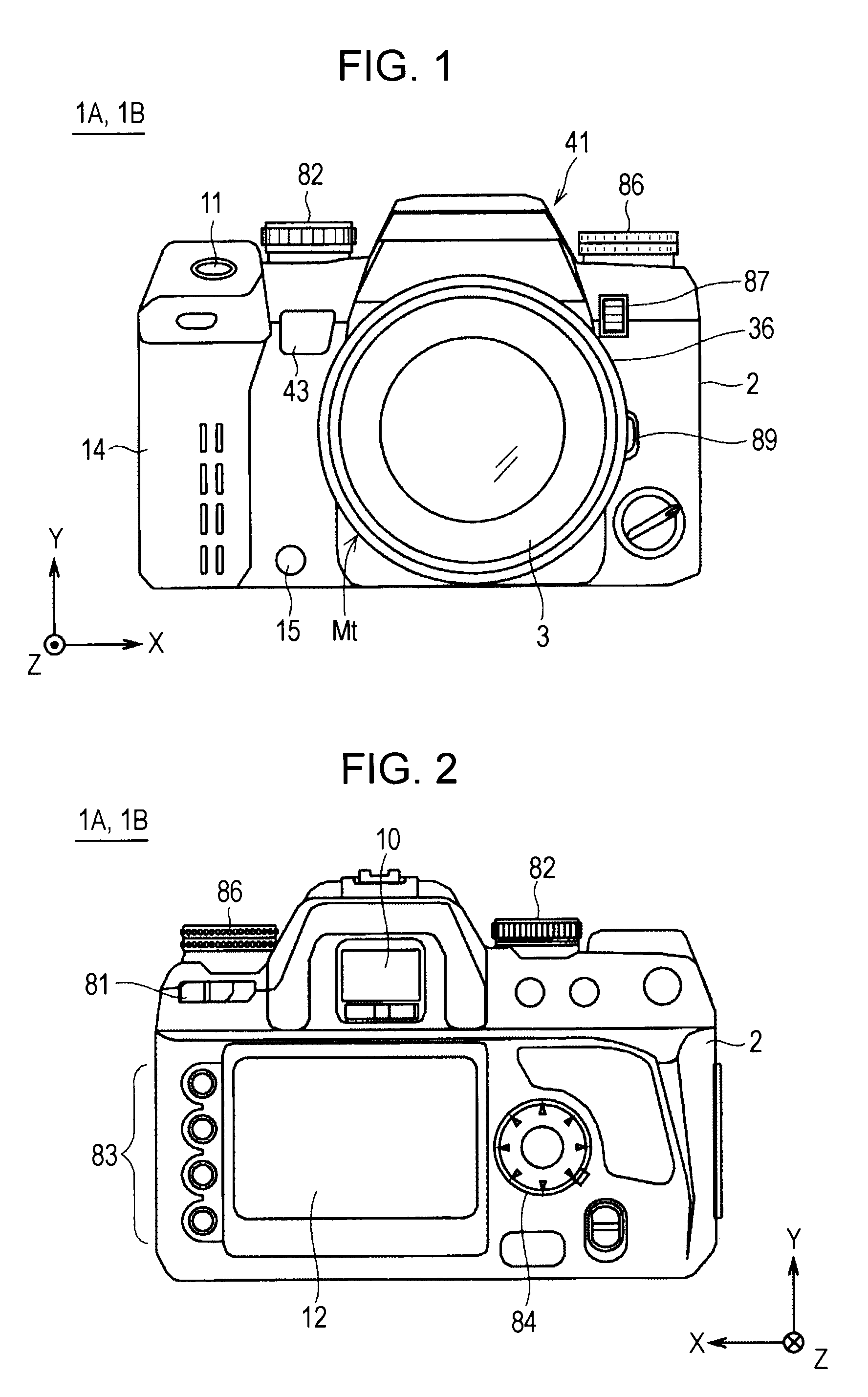
[0022]FIGS. 1 and 2 are diagrams showing an exterior structure of an image pickup apparatus 1A according to a first embodiment of the present invention. Here, FIG. 1 is a front view showing the exterior structure of the image pickup apparatus 1A. FIG. 2 is a back view showing the exterior structure of the image pickup apparatus 1A. The image pickup apparatus 1A is a digital SLR camera with an interchangeable lens.

[0023]As shown in FIG. 1, the image pickup apparatus 1A includes a camera main body (a camera body) 2. An interchangeable lens unit (an interchangeable lens) 3 is detachable from the camera main body 2.

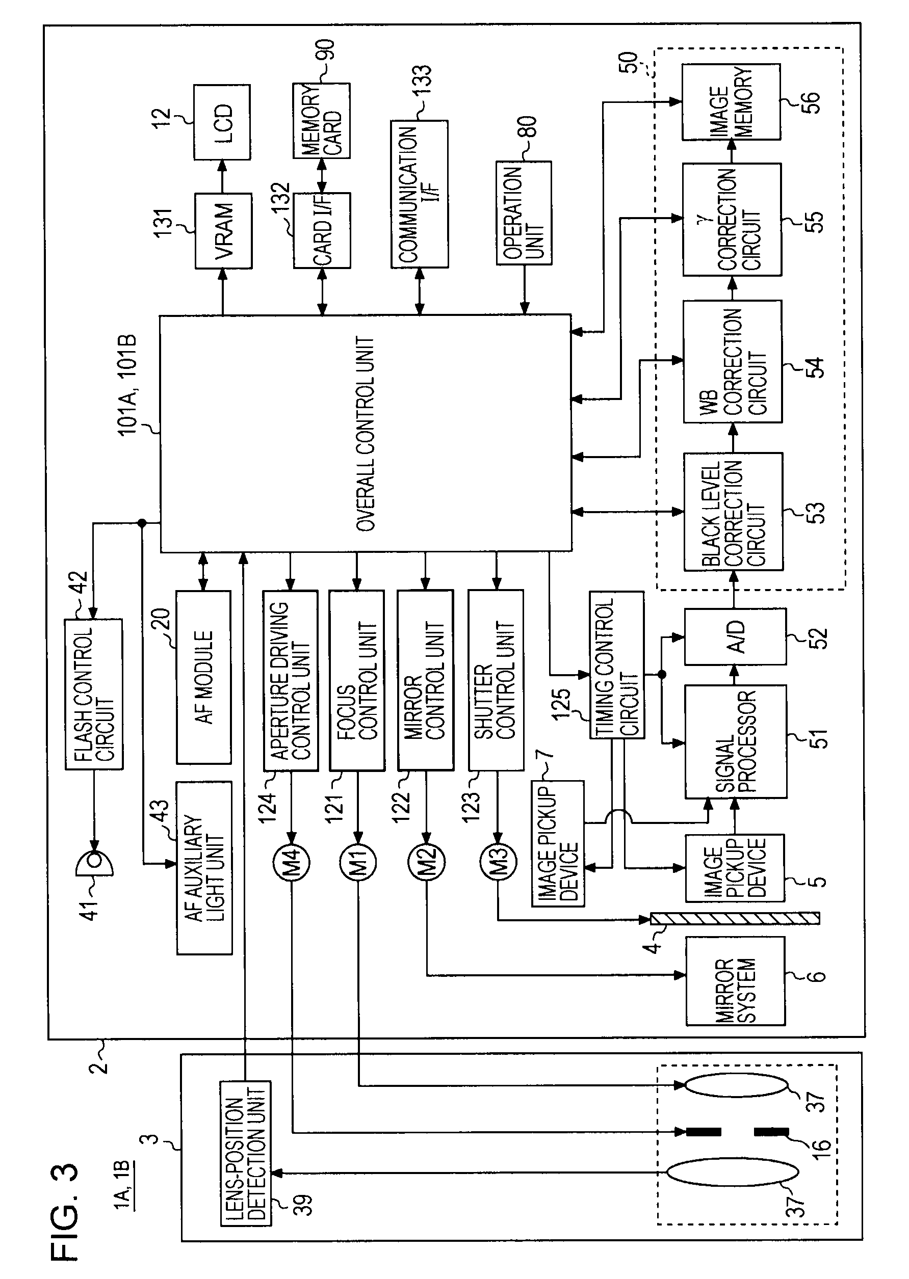
[0024]The interchangeable lens unit 3 mainly includes a barrel 36 and a shooting optical system provided inside the barrel 36. The shooting optical system includes, for example, lenses 37 (see FIGS. 3 through 5) and an aperture 16 (see FIG. 3). The lenses 37 include, for example, a focus lens that changes a focus position by moving along an optical axis.

[0025]The camera main ...

second embodiment

[0094]An image pickup apparatus 1B according to a second embodiment of the present invention is structurally similar to the image pickup apparatus 1A, as shown in FIGS. 1 through 3, according to the first embodiment of the present invention. However, an overall control unit 101B is structurally different from the overall control unit 101A.

[0095]More particularly, dissimilar to the first embodiment, the image pickup apparatus 1B can perform an operation of customized allocation of a function to the preview key 15 to be used in the case in which the EVF is used, and a program for performing this operation of the customized allocation is stored in a ROM of the overall control unit 101B. In the following, an operation of the image pickup apparatus 1B will be described in detail with respect to the customized allocation of a function to the preview key 15.

[0096]FIG. 7 is a flowchart showing an operation of the customized allocation of a function to the preview key 15. FIGS. 8 through 10 ...


PUM


Abstract

An image pickup apparatus with a specific operation member for accepting an operation input includes a image pickup unit configured to receive a light image of a subject and generate an image signal, a display unit configured to display an image on the basis of the image signal, an electronic finder unit configured to cause the display unit to display the image relating to the light image before performance of a main shooting process on the basis of image signals generated in sequence by the image pickup unit, an optical finder unit configured to guide the light image to a finder window, and an allocation unit configured to allocate a function to the specific operation member in the case in which the optical finder unit is used and another function to the specific operation member in the case in which the electronic finder unit is used.

Description

CROSS REFERENCES TO RELATED APPLICATIONS[0001]The present invention contains subject matter related to Japanese Patent Application JP 2007-116618 filed in the Japanese Patent Office on Apr. 26, 2007, the entire contents of which are incorporated herein by reference.BACKGROUND OF THE INVENTION[0002]1. Field of the Invention[0003]The present invention relates to an image pickup apparatus having a predetermined operation member for accepting an operation input.[0004]2. Description of the Related Art[0005]Some image pickup apparatuses, for example, a digital camera, are capable of allowing allocation of a function to a specific operation member to improve operability.[0006]For example, Japanese Unexamined Patent Application Publication No. 2005-266991 discloses an image pickup apparatus capable of realizing a desired function easily by allowing an operation member (for example, a specific button) to be allocated with a predetermined function which is frequently used by a user and allowi...

Claims


Application Information

Patent Timeline
IPC IPC(8): H04N5/222G03B7/00G03B13/06G03B17/02G03B19/12H04N5/225
CPCG03B7/006G03B13/06G03B17/02G03B19/12H04N5/23216H04N5/23219H04N5/23293H04N2101/00H04N23/672H04N23/61H04N23/62H04N23/611H04N23/632H04N23/635
Inventor OKAZAKI, TAKASHI
Owner SONY CORP
Why Eureka
Try Eureka