
Combustion Method and System

a combustion system and combustion method technology, applied in the direction of combustion types, fuel supply regulation, lighting and heating apparatuses, etc., can solve the problems of prior art devices that cannot recognize the change and devices based on the technology often do not achieve the optimum nox reduction, and devices that cannot quickly, or cannot quickly, adjust the operating parameters, etc., to reduce the difference, reduce slagging, and reduce nox emission

Inactive Publication Date: 2008-10-16
CLEAN COMBUSTION TECH
View PDF8 Cites 6 Cited by
  • Summary
  • Abstract
  • Description
  • Claims
  • Application Information

AI Technical Summary

Benefits of technology

[0010]The present invention is directed to a method of combustion that has one or more advantages of low NOx emission, low unburned carbon, automatic adaptability to any types of fossil fuel, and reduced slagging. The combustion method may include injecting a air / fuel stream into a burner to cause a low-pressure zone; directing a flow of a high-temperature combustion gas from a combustion chamber into the low-pressure zone in the burner; mixing the high-temperature combustion gas with the injected air / fuel stream to heat the injected air / fuel stream, and injecting the heated air / fuel stream from the burner to the combustion chamber, wherein the air / fuel stream is rapidly devolatilized and combusted in a flame; sensing a combustion parameter; and based on the sensed combustion parameter, controlling the combustion to achieve at least one of a desired NOx reduction and a desired distance from the burner to a front of the flame. In a preferred embodiment, the combustion is controlled to maximize NOx reduction without impermissible slagging. What constitutes “impermissible slagging” cannot be determined in the abstract and must be determined on a case-by-case basis from the design requirements for a given combustion system. Such a determination can be made by a person with ordinary skill in the art.
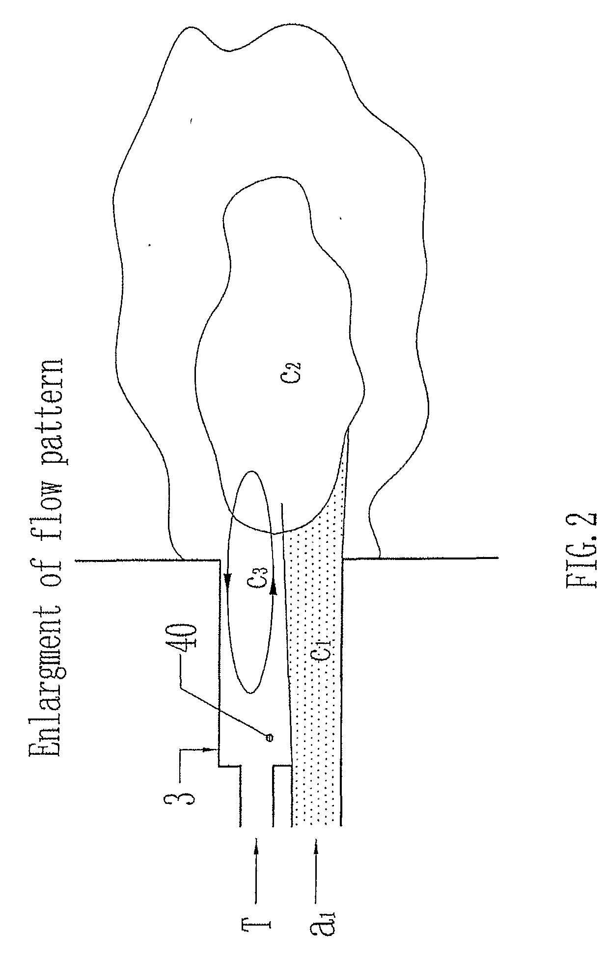
[0012]In a preferred embodiment, the velocity of the injected air / fuel stream in the burner is 10 to 60 m / sec, more preferably 15 to 50 m / sec. The velocity can be designed so as to feed the air / fuel stream without blocking the feed pipe, and to introduce a pressure inside the burner that is lower than that in the combustion chamber. The cross-sectional area of the injection at the entrance of the burner may be a fraction of the cross-sectional area of the burner, preferably 20% to 60%. The desirable ratio of the two cross-sectional areas allows a certain amount of high-temperature combustion gas to flow back into the burner from the combustion chamber.
[0014]There are several reasons for the use of a concentrated air / fuel stream. First, the concentrated stream allows the maintenance of a highly fuel-rich flame inside the burner and combustion chambers, which can significantly reduce the NOx. Secondly, the concentrated stream can be heated up using a relatively small amount of heat. Thus the concentrated stream can be quickly heated up in a short distance. Third, the heated concentrated stream releases a large amount of volatiles in the fast heating. (Partial combustion also may take place during the heating of the concentrated stream.) The released volatiles enhance the ignition and combustion of the coal particles, reducing the unburned carbon in fly ash. Additionally, a fast release of volatiles including fuel-bound nitrogen in the fuel rich atmosphere allows transformation of the fuel-bound nitrogen into N2 rather than NOx. The overall effects of the concentrated air / fuel stream and the designed burner allow combustion to be performed and maintained at a high temperature and in an atmosphere of reduced gases, which is conductible to ultra-low NOx emission and low unburned carbon in fly ash.
[0022]Combustion control can be achieved by controlling the pressure in the low-pressure zone, because the pressure in the low-pressure zone affects the flow rate of the high-temperature combustion gas from the combustion chamber into the low-pressure zone in the burner and, thus, the heating of the air / fuel stream. The pressure in the low-pressure zone can be controlled by introducing a gas into the low pressure reflow zone. Preferably, the gas is air (tertiary air). When the quantity of tertiary air is increased, the pressure in the low-pressure zone is also increased, resulting in a decreased flow of the high-temperature combustion gas from the combustion chamber into the low-pressure zone. As a result, the heating of the air / fuel stream is reduced, and combustion temperature may be reduced. The amount of tertiary air affects also the air / fuel weight ratio of the air / fuel stream, which can also be used for combustion control.
[0024]The combustion control of the present invention can be based on one or more combustion parameters. Representative parameters may be combustion temperature, pressure, and the concentration of one or more selected gases such as carbon dioxide, carbon monoxide, oxygen and nitrogen. Preferably, the temperature is used as the combustion parameter. The control may be realized by sensing the value of the combustion parameter inside the burner and / or the combustion chamber, and comparing the sensed value with a preset value. Based on the difference between the sensed value and preset value, the controller, such as a close-loop controller or a distributed control system, adjusts one or more of the above-discussed control parameters to reduce the difference. When the difference is reduced, the NOx emission is reduced, and / or a desired distance from the burner to a flame front is maintained to reduce slagging. This automatic control enables a burner to be used with almost all kinds of fuel without changing the structure of the combustion system.

Problems solved by technology

One of the problems is that although the prior art technologies for reducing NOx are based on solid theories, the devices based on the technologies often do not achieve optimum NOx reduction.
The reason is that those devices do not, or cannot quickly, adjust operating parameters to adapt to changing operating conditions for optimum NOx reduction.
For example, when the quality or type of coal changes or when the load is changed, the prior art devices do not, or cannot quickly, recognize the change and adjust the operating parameters to adapt to the change.
As a result, an optimum NOx reduction cannot be achieved for the coal being used.
Another problem associated with the prior art is that, in the case of the technology involving feeding high-temperature gas to coal, which produces high combustion temperature, the failure to adjust operating parameters to adapt to changing operating conditions may result in the flame front becoming too close to the wall of the burner and / or the wall of the combustion chamber.
As a result, slagging takes place on the wall of the burner and / or the wall of the combustion chamber.
For example, the inventors' experiment shows that when the operating parameters are set for anthracite coal (with volatile of 7.36%) but bituminous coal (with volatile of 17.22%) is used, slagging takes place on the wall of the burner due to over-heating and can cause a shout-down of the combustion system.

Method used


Image

  • Combustion Method and System
  • Combustion Method and System
  • Combustion Method and System

Examples


Embodiment Construction

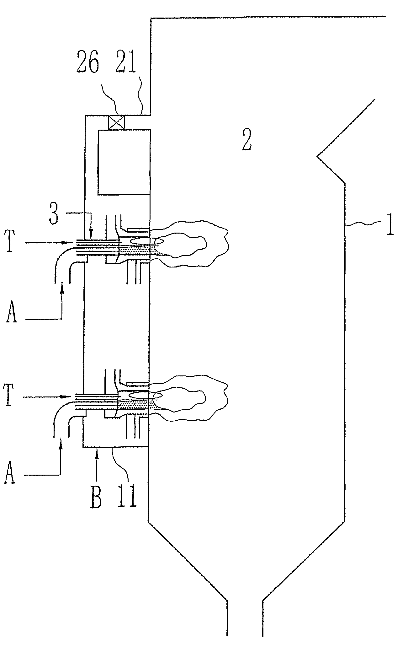
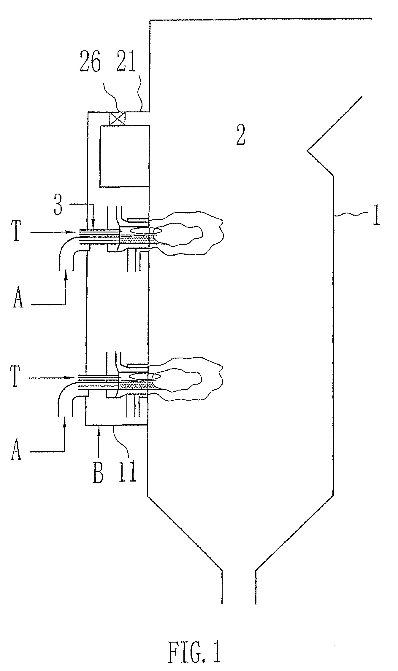
[0033]The preferred embodiments of the present invention described below are discussed sometimes in terms of coal combustion, and in terms of air being the gaseous carrier and oxidant. The techniques described are applicable to any other pulverized solid fuel and any other gaseous carrier. The invention will be described with the aid of the Figures, yet a description that refers to the Figures is not used to limit the scope of the invention.

[0034]FIG. 1 to 4 show a preferred embodiment of a swirling burner according to the present invention. Some embodiments of the burner are described in more detail in FIGS. 4 and 5. The invention also encompasses straight-flow burners where the secondary stream or / and the other streams is (are) fed into the combustion chamber in a straight flow.

[0035]FIG. 1 shows a combustion system includes a burner 3 and a combustion device 1 having a chamber 2. The combustion device of the present invention can be any apparatus within which combustion takes pla...


PUM


Abstract

A method of combustion for pulverized hydrocarbonaceous fuel includes the steps of injecting an air / fuel stream into a burner, causing a low-pressure zone; directing a flow of a high-temperature combustion gas from a combustion chamber into the low-pressure zone in the burner; mixing the high-temperature combustion gas with the injected air / fuel stream to heat the injected air / fuel stream, and injecting the heated air / fuel stream from the burner to the combustion chamber, wherein the air / fuel stream is rapidly devolatilized and combusted in a flame that has a high temperature; sensing a combustion parameter; and based on the sensed combustion parameter, controlling combustion to achieve at least one of a desired NOx reduction and a desired distance from the burner to a flame front.

Description

TECHNICAL FIELD OF THE INVENTION[0001]The present invention relates to a combustion method, and a combustion system, for solid hydrocarbonaceous fuel.BACKGROUND OF THE INVENTION[0002]Solid fossil fuel, such as coal, is an important energy source, particularly for power generation. Pollutants emitted from coal combustion, however, are a major source of air pollution. Of the pollutants from coal combustion, nitrogen oxides (NOx) have attracted extensive attention.[0003]There are two primary sources of NOx generated during combustion: fuel NOx and thermal NOx. Fuel NOx is NOx formed due to the conversion of chemically bound nitrogen (fuel nitrogen) during combustion. Fuel nitrogen (or char-N) is released in several complex combustion processes. The primary initial product of combustion is either HCN or NH3. HCN is then either oxidized to NO or reduced to N2. If the gases are oxidant or the fuel is lean, NO will be the dominant product of fuel nitrogen. If it is fuel rich, HCN is reduce...

Claims


Application Information

Patent Timeline
Patent Type & Authority Applications(United States)
IPC IPC(8): F23C1/12F23C6/04
CPCF23C2900/99004F23D1/00F23D2201/20F23K1/04F23N1/022F23N2023/36F23N2039/02F23N2223/36F23N2239/02
Inventor JIA, ZHENZENG, TAOFANGJIA, XIAOGUANGLI, XING
Owner CLEAN COMBUSTION TECH
Learn More