
Piezo actuated slide latching mechanism

a technology of latching mechanism and slide, which is applied in the direction of fastening means, mechanical devices, furniture parts, etc., can solve the problems of large and heavy mechanism, inconvenient use, complex electro-mechanical system, etc., and achieves the effect of reducing the difficulty of thwarting various locks and preventing the movement of the lock

Active Publication Date: 2008-10-09
CAREFUSION 303 INC
View PDF15 Cites 34 Cited by
  • Summary
  • Abstract
  • Description
  • Claims
  • Application Information

AI Technical Summary

Benefits of technology

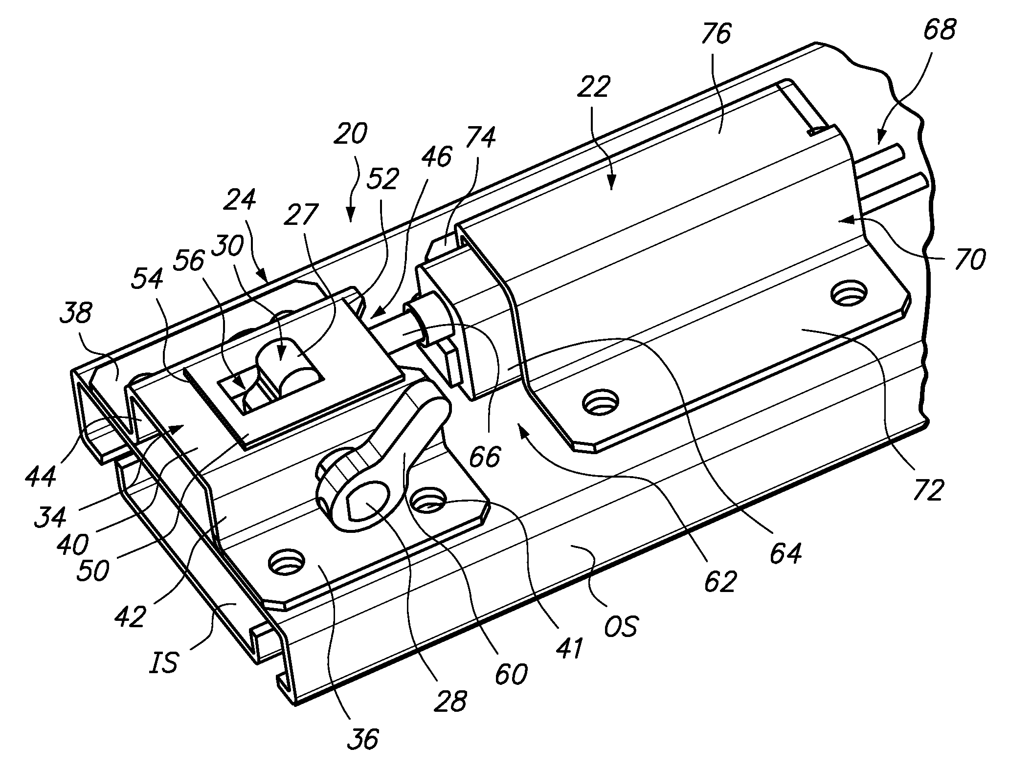
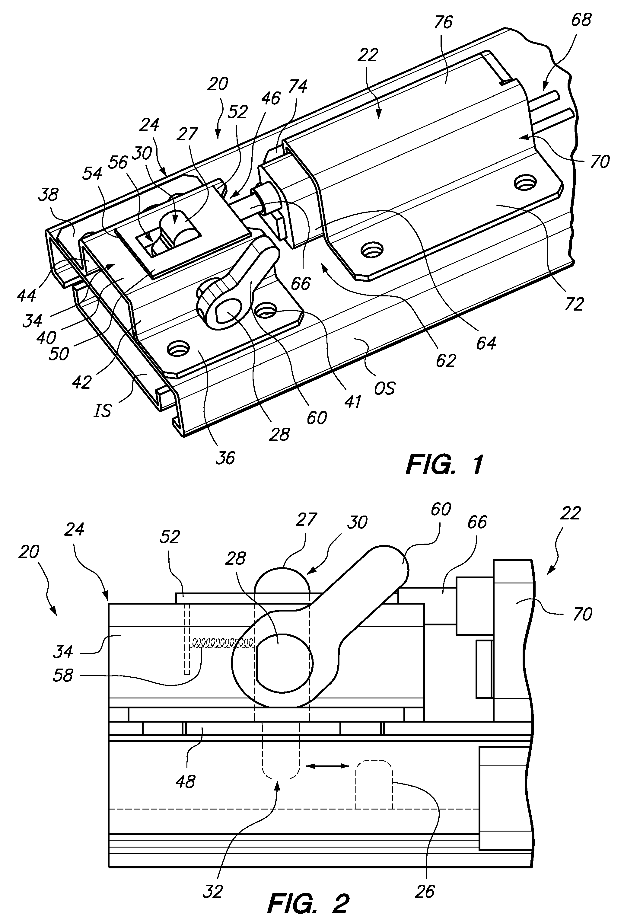
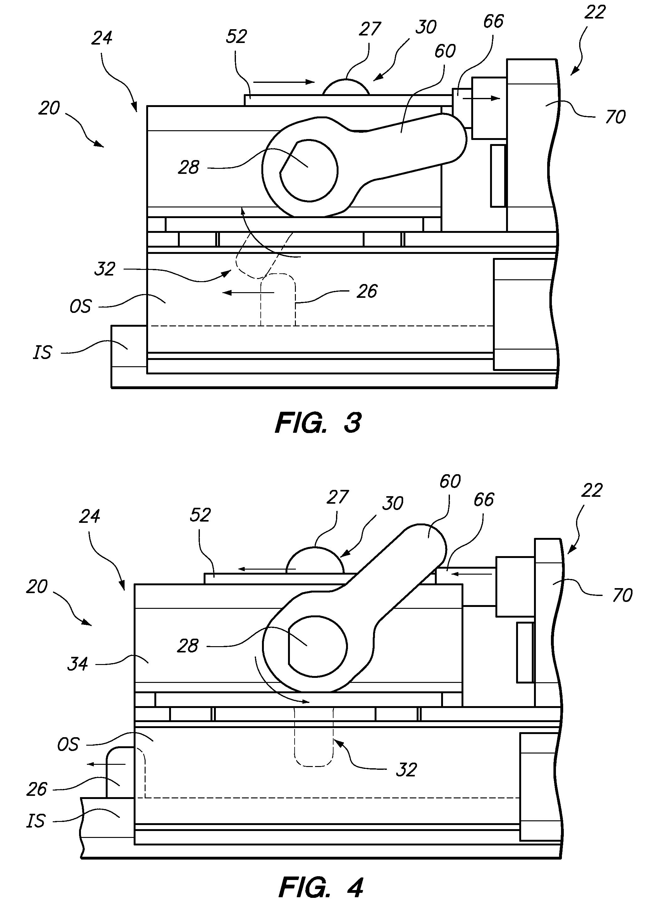
[0011]Outward movement of the second slide is prevented by engagement of the latch tab with the second end of the latch lever. In particular, in its locked position, the latch lever is prevented from rotating to an unlocked position by the plunger.

Problems solved by technology

In some instances, the mechanisms are large and heavy and are not suited use in many environments where such drawers are utilized.
Various of the electro-mechanical systems are complex or require that power be provided at all times in order to ensure that the drawer remains locked.
In addition, various of these locks can be relatively easily thwarted, such as by application of force, picking the lock or the like.

Method used


Image

  • Piezo actuated slide latching mechanism
  • Piezo actuated slide latching mechanism
  • Piezo actuated slide latching mechanism

Examples


Embodiment Construction

[0022]In the following description, numerous specific details are set forth in order to provide a more thorough description of the present invention. It will be apparent, however, to one skilled in the art, that the present invention may be practiced without these specific details. In other instances, well-known features have not been described in detail so as not to obscure the invention.

[0023]One embodiment of the invention is a latching mechanism. The latching mechanism has particular applicability to a slide, such as used to permit movement of a drawer. In general, the latching mechanism comprises a first latching member for selective engagement with a second latching member, and an actuator or controller which selectively controls the first latching member.

[0024]The first latching member may comprise a latch assembly associated with an outer slide member. The second latching member may comprise a tab associated with an inner slide member. The controller preferably comprises a p...


PUM


Abstract

A latching mechanism is particularly suited for use in latching a slide mechanism, such as used to slidably mount a drawer. The latching mechanism includes a latch assembly comprising a latch lever mounted for movement between a first, second and third positions, a latch tab for selective engagement with a second end of the latch lever, and a piezo electric controller. The controller has a plunger configured to selectively control the movement of the latch lever between the first and second positions, the plunger movable between an extended position corresponding to a first, locked position of the latch lever and a retracted position corresponding to the second, unlocked position of the latch lever, the controller when unpowered preventing the plunger from moving from the extended to the retracted position and the controller when powered permitting the plunger to move from the extended to the retracted position.

Description

FIELD OF THE INVENTION[0001]The present invention relates to locking or latching mechanisms and, more particularly, such mechanisms for use in locking or latching a slide, such as used with a drawer.BACKGROUND OF THE INVENTION[0002]It is often desirable to lock a drawer in its closed position in order to prevent access to the interior thereof. For example, medication, medical devices, or sensitive documents might be stored in the drawer.[0003]A variety of locking or latching mechanisms have been developed for such a purpose. For example, mechanical locks are known which utilize key to rotate a latching member from a retracted position to an extended position in which the member interferes with the movement of the drawer. Some locking mechanisms are electro-mechanical, such as using a motor to move the locking member.[0004]In general, prior drawer locking mechanisms have one or more drawbacks. In some instances, the mechanisms are large and heavy and are not suited use in many enviro...

Claims


Application Information

Patent Timeline
Patent Type & Authority Applications(United States)
IPC IPC(8): E05C1/00
CPCE05B47/00E05B65/46E05B47/0011Y10T292/096Y10T292/1021Y10T292/102
Inventor OSTROWSKI, ERIC ALLEN
Owner CAREFUSION 303 INC
Learn More