
Catheter malfunction determinations using physiologic pressure

a technology of physiologic pressure and catheter, applied in the field of catheter malfunction determinations using physiologic pressure, can solve the problems of catheter leakage, catheter obstructing or clogging during use, and catheters can have and/or develop operational problems

Active Publication Date: 2008-10-02
MEDTRONIC INC
View PDF101 Cites 17 Cited by
  • Summary
  • Abstract
  • Description
  • Claims
  • Application Information

AI Technical Summary

Benefits of technology

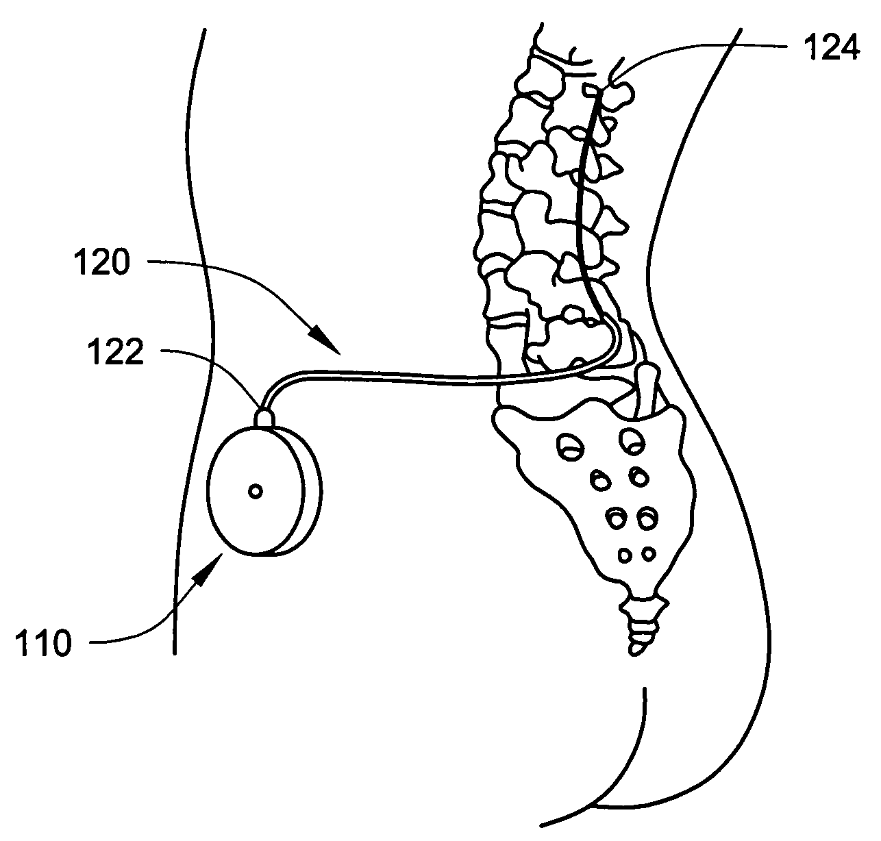
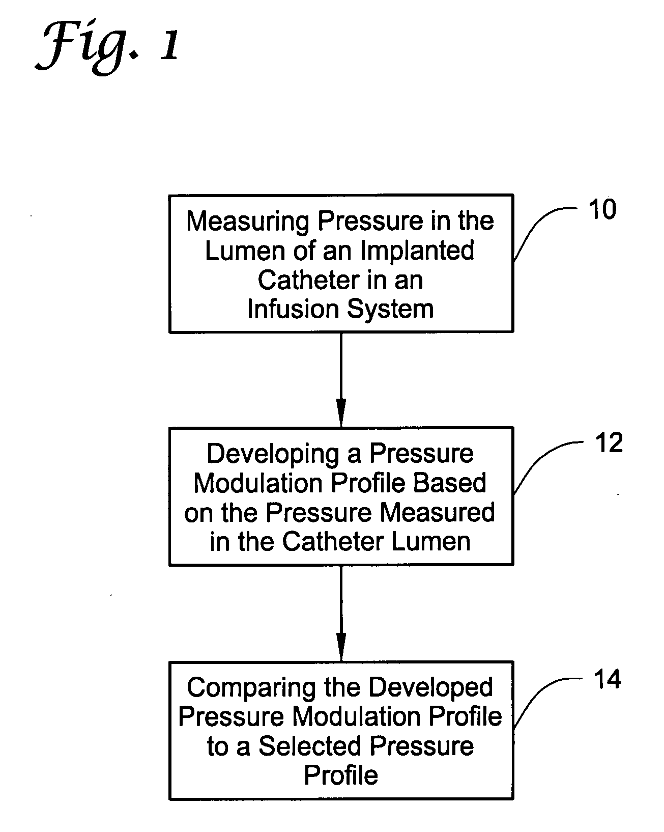
[0021]In another aspect, the present invention provides an implantable infusion system that includes a pump mechanism fluidly coupled to a reservoir to receive fluid contained within the reservoir; a catheter having a delivery lumen fluidly coupled to the pump mechanism, wherein the delivery lumen extends to an implantable infusion section in the catheter; a pressure sensor positioned to monitor fluid pressure within the delivery lumen of the catheter and provide a pressure signal representative of the fluid pressure; and control electronics connected to receive the pressure signal from the pressure sensor, wherein the control electronics develops a pressure modulation profile based on the fluid pressure measured in the delivery lumen and compares the pressure modulation profile to a selected pressure profile.
[0022]In another aspe

Problems solved by technology

While perhaps the least complex component of an infusion system, catheters can have and / or can develop operational problems.
For example, catheters may be placed in the wrong location when originally deployed or the catheters may move (migrate) over time such that fluids (e.g., therapeutic substances) delivered through the catheters are not delivered to the selected internal delivery site.
Catheters can also become obstructed or clogged during use.
Catheters can also leak due to cuts, tears, etc.
In addition to the lack of therapeutic substance supplied to the selected internal delivery site of the patient, the therapeutic substance could be dispersed outside of the selected internal delivery site which may create further issues.

Method used


Image

  • Catheter malfunction determinations using physiologic pressure
  • Catheter malfunction determinations using physiologic pressure
  • Catheter malfunction determinations using physiologic pressure

Examples


Embodiment Construction

[0032]In the following detailed description of illustrative embodiments of the invention, reference is made to the accompanying figures of the drawing which form a part hereof, and in which are shown, by way of illustration, specific embodiments in which the invention may be practiced. It is to be understood that other embodiments may be utilized and structural changes may be made without departing from the scope of the present invention.

[0033]It is noted that the terms “comprises” and variations thereof do not have a limiting meaning where these terms appear in the accompanying description and claims. Moreover, “a,”“an,”“the,”“at least one,” and “one or more” are used interchangeably herein.

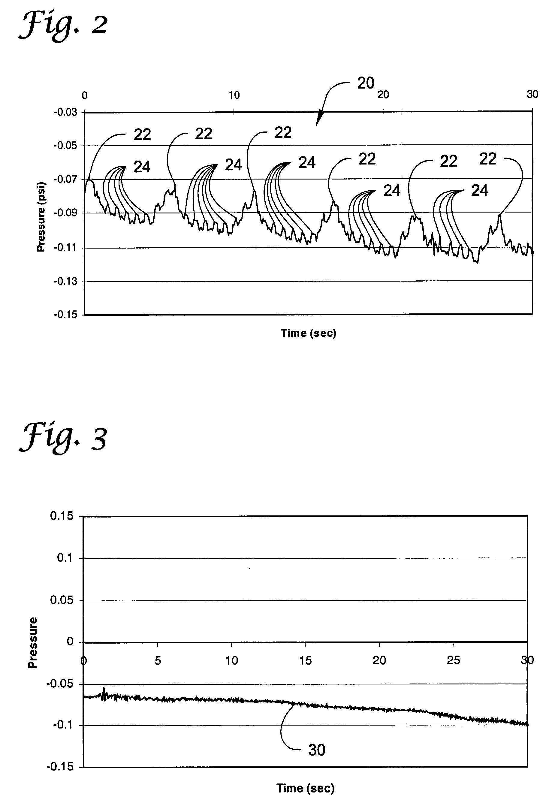
[0034]As discussed herein, the methods and systems of the present invention involve monitoring fluid pressure within the fluid-filled lumen of a catheter where the fluid in the lumen is in fluid communication with the physiological pressure at a selected internal delivery site. The infusion sect...


PUM


Abstract

Methods and systems for determining whether an implanted catheter used to deliver fluids to a selected internal delivery site is malfunctioning. The malfunctions may include that the infusion section of the catheter is not located at or has migrated away from the selected internal delivery site, is leaking, is blocked, etc. The determination is made by analyzing the pressure modulation of fluid within the catheter and determining whether the pressure of the fluid in the catheter is modulated by physiologic pressure changes experienced at the selected internal delivery site. The physiologic pressure modulations at the selected internal delivery site may be caused by, e.g., cardiac activity, respiration, changes in patient's posture, etc.

Description

TECHNICAL FIELD[0001]The present invention relates generally to systems and methods for identifying malfunctions in the implanted catheter of an infusion system by sensing fluid pressure within the catheter.BACKGROUND[0002]Infusion systems may be used, for example, when administration of a therapeutic substance (e.g., a pharmaceutically active agent) to an internal delivery site within a patient is desired. The internal delivery sites may include, e.g., vascular delivery (arterial, venous, etc.), intraparenchymal solid organ sites (e.g., Ipa brain, liver, etc.), intrathecal locations (containing the cerebrospinal fluid (CSF) of a patient), etc. An implantable infusion system including a catheter may be preferred when it is important to deliver the therapeutic substance to the internal delivery site in controlled, often minute, dosages.[0003]Typically, an infusion system includes a reservoir containing a supply of therapeutic substance awaiting delivery to a the patient. A pump may b...

Claims


Application Information

Patent Timeline
IPC IPC(8): A61M25/095
CPCA61M5/14276A61M5/16859A61M2005/1726A61M2202/0464
Inventor MIESEL, KEITH A.COFFEY, ROBERT J.
Owner MEDTRONIC INC
Learn More