Roller Clutch Assembly

Inactive Publication Date: 2008-09-25
NG PHILIP +1
View PDF16 Cites 3 Cited by
  • Summary
  • Abstract
  • Description
  • Claims
  • Application Information

AI Technical Summary

Benefits of technology

[0004]In accordance with one aspect of the present invention, there is provided a roller clutch assembly for a roller blind which overcomes the disadvantages of the prior art by providing smooth and quite operation. The roller clutch assembly includes an elongated roller tube having first and second opposite ends and a clutch coaxially mounted to the first end of the tube. The clutch has a peripheral section rotatably mounted to a fixed hub, the peripheral section being mounted to the tube such that the tube is free to rotate. The assembly also includes an elongated rod mounted within the roller tube, the rod having opposite first and second ends, the first end of the rod being mounted to the hub of the clutch. A mount is rotatably mounted on the second end of the rod for mounting the second end of the rod securely within the tube. A coil spring is coaxially mounted onto the elongated rod, the coil spring having opposite first and second ends, the first end of the spring being fixed to the rod adjacent the first end of the rod, the second end of the spring being fixed to the mounting adaptor such that the spring can be wound and unwound on the rod by rotating the tube.

Problems solved by technology

While such spring loaded clutch assemblies are popular, they suffer from one annoying problem, namely such spring loaded clutch assemblies tend to rattle as they are rolled up and down.
The rattle is due to the spring being not fully supported within the roller tube and / or kinking.
As a result, the spring loading mechanism has a tendency to hit against the roller tube during operation, causing a rattling sound.

Method used


Image

  • Roller Clutch Assembly
  • Roller Clutch Assembly
  • Roller Clutch Assembly

Examples


Embodiment Construction

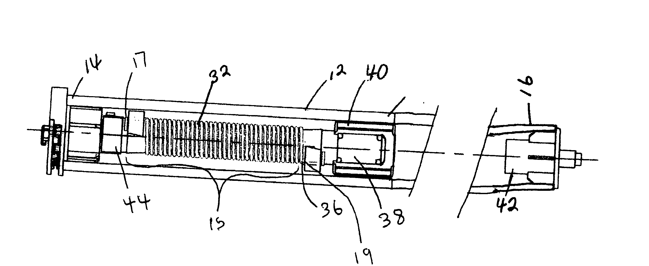
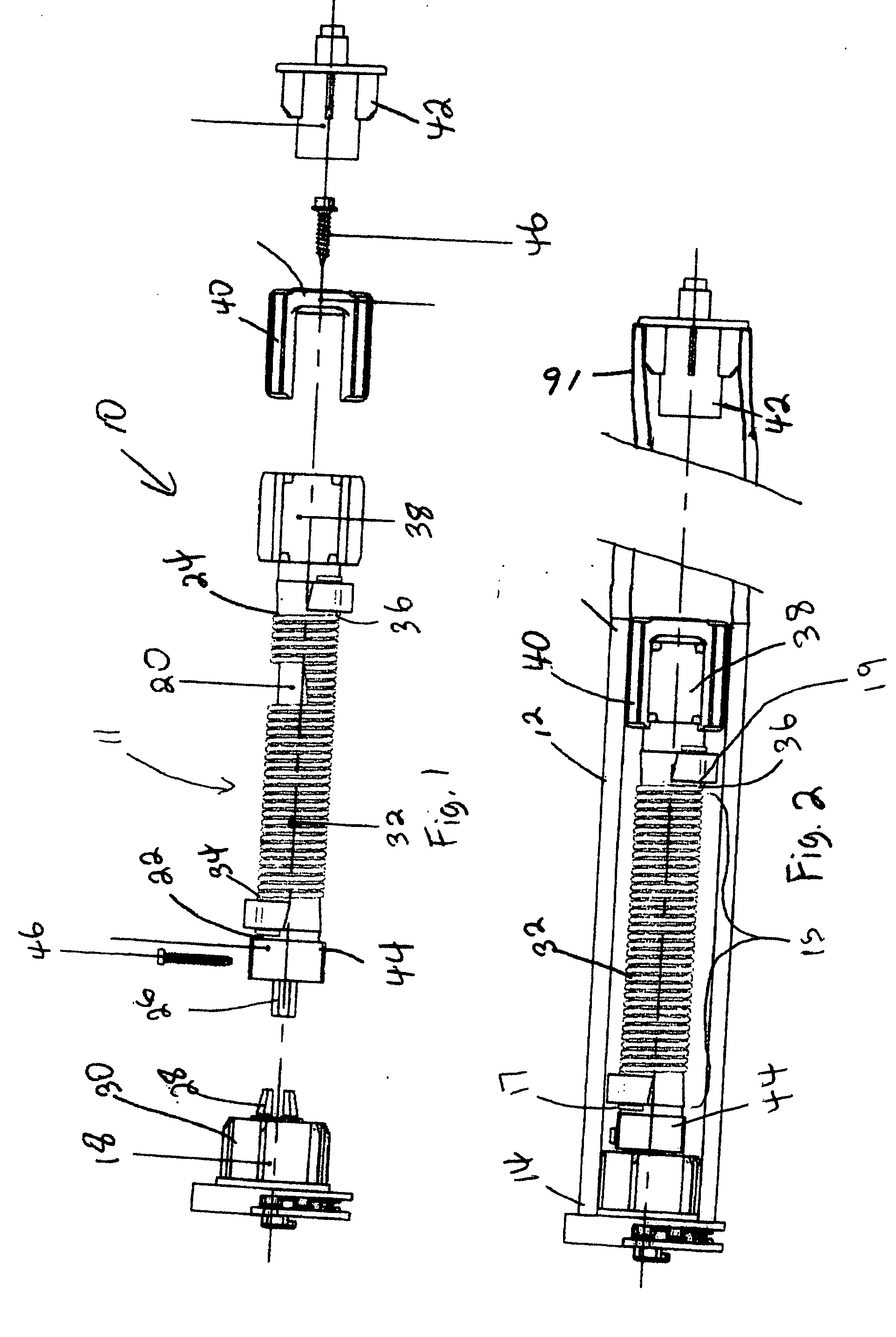
[0013]Referring firstly to FIG. 3, prior art spring assist assemblies, shown generally as item 100, consisted of an elongated coil spring 110 which was mounted within a roller tube 112 mounted between clutch 114 and support 120. The coil spring had opposite ends 122 and 124 which were attached to clutch 114 and support 120, respectively. As the roller tube 112 was rotated, coil spring 110 would be either wound (loaded) or unwound (unloaded) depending on the direction the tube was rotated. Generally, the spring was mounted in the tube such that the spring was loaded (coiled up) as the blind (not shown) wrapped onto the tube was lowered and unloaded as the blind was raised. As the spring is coiled it has a tendency to kink as shown in FIG. 3. Kinks 116 and 118 tend to bulge out and make contact with tube 112, causing an annoying clinking sound as the blind is lowered or lifted. The present invention overcomes this disadvantage by providing a design which keeps the spring coaxially ali...


PUM


Abstract

The present invention is a roller clutch assembly for a roller blind which operates smoothly and quietly. The roller clutch assembly includes an elongated roller tube having first and second opposite ends and a clutch coaxially mounted to the first end of the tube. The clutch has a peripheral section rotatably mounted to a fixed hub, the peripheral section being mounted to the tube such that the tube is free to rotate. The assembly also includes an elongated rod mounted within the roller tube, the rod having opposite first and second ends, the first end of the rod being mounted to the hub of the clutch. A mount is rotatably attached to the second end of the rod for mounting the rod within the tube such that the tube and rod are substantially coaxially aligned. A coil spring is coaxially mounted onto the elongated rod, the coil spring having opposite first and second ends, the first end of the spring being fixed to the rod adjacent the first end of the rod, the second end of the spring being fixed to the mounting adaptor such that the spring can be wound and unwound on the rod by rotating the tube. The spring is stretched onto the rod sufficiently such that the spring does not kink when wound.

Description

CROSS REFERENCE TO RELATED APPLICATION[0001]This application claims priority from U.S. provisional patent application Ser. No. 60 / 880,017 filed Jan. 12, 2007, the entirety of which is incorporated herein by reference.FIELD OF THE INVENTION[0002]The invention relates generally to spring loaded roller clutch assemblies for roller blinds.BACKGROUND OF THE INVENTION[0003]Spring loaded clutch assemblies for use with roller blinds are well known in the art. These clutch assemblies generally include a roller tube for taking up the blind and a clutch for winding the roller tube. A long coil spring is usually disposed inside the roller tube to permit a spring assist when pulling up the roller blind. While such spring loaded clutch assemblies are popular, they suffer from one annoying problem, namely such spring loaded clutch assemblies tend to rattle as they are rolled up and down. The rattle is due to the spring being not fully supported within the roller tube and / or kinking. As a result, t...

Claims


Application Information

Patent Timeline
IPC IPC(8): E06B9/56
CPCE06B9/60E06B9/42
Inventor NG, PHILIPWILLS, NORMAN
Owner NG PHILIP
Why Eureka
Try Eureka