
Position detecting apparatus, position inputting apparatus, and computer including the same

a technology of position inputting apparatus and detecting apparatus, which is applied in computing, instruments, and details of portable computers, etc., can solve problems such as interference and viewing problems on display apparatus, and achieve the effect of not compromising the quality of images on display apparatus

Active Publication Date: 2008-09-18
WACOM CO LTD
View PDF1 Cites 18 Cited by
  • Summary
  • Abstract
  • Description
  • Claims
  • Application Information

AI Technical Summary

Benefits of technology

[0011]The present invention also provides a display apparatus for displaying images by changing states of a plurality of display elements arrayed in a predetermined direction and a position detecting apparatus combined with the display apparatus for detecting a position indicated on the display apparatus, in which even when a plurality of loop coils is located close to the display apparatus, it is possible to prevent problems associated with interference and a moire pattern(s) from being produced on the display apparatus.
[0029]According to the position detecting apparatus, the position inputting apparatus and the computer described above, the display apparatus and the position detecting apparatus can be combined to operate in a satisfactory manner. Also, even when a plurality of loop coils are located close to the display apparatus, it is possible to prevent problems associated with interference and a moire pattern(s) from being produced on the display apparatus. As a result, quality of images on the display apparatus are not compromised by the loop coils.

Problems solved by technology

However, when the position detecting apparatus is provided at the back side of the display apparatus, the position detecting apparatus restricts a design of the display apparatus and location of a driving circuit for the display apparatus located at the back side of the position detecting apparatus.
The moire pattern(s) causes interference and viewing problems on the display apparatus.

Method used


Image

  • Position detecting apparatus, position inputting apparatus, and computer including the same
  • Position detecting apparatus, position inputting apparatus, and computer including the same
  • Position detecting apparatus, position inputting apparatus, and computer including the same

Examples


Embodiment Construction

[0037]Reference will now be made in detail to the embodiments and methods of the invention as illustrated in the accompanying drawings, in which like reference characters designate like or corresponding parts throughout the drawings. It should be noted, however, that the invention in its broader aspects is not limited to the specific details, representative devices and methods, and illustrative examples shown and described in this section in connection with the embodiments and methods. The invention according to its various aspects is particularly pointed out and distinctly claimed in the attached claims read in view of this specification, and appropriate equivalents.

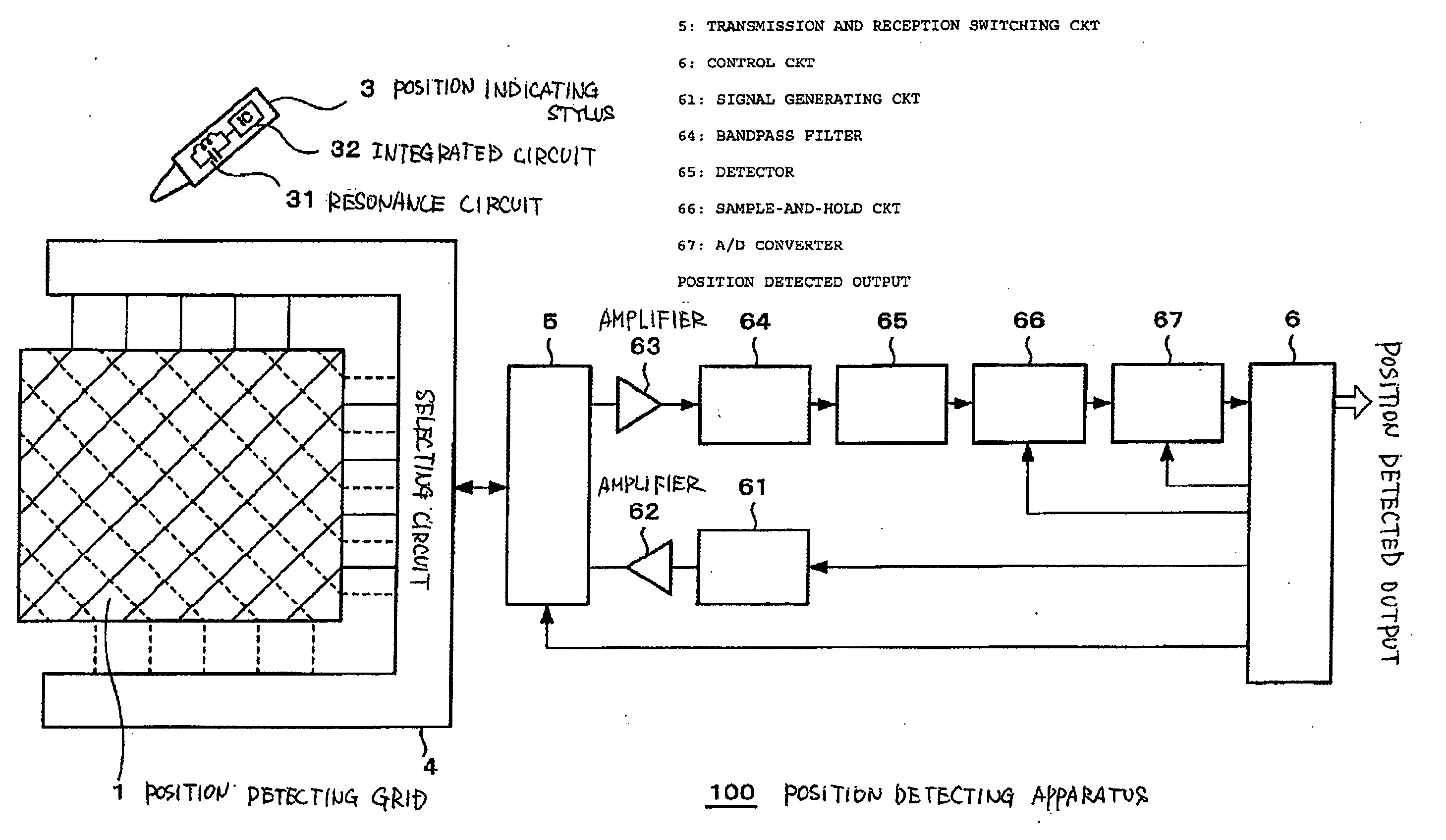
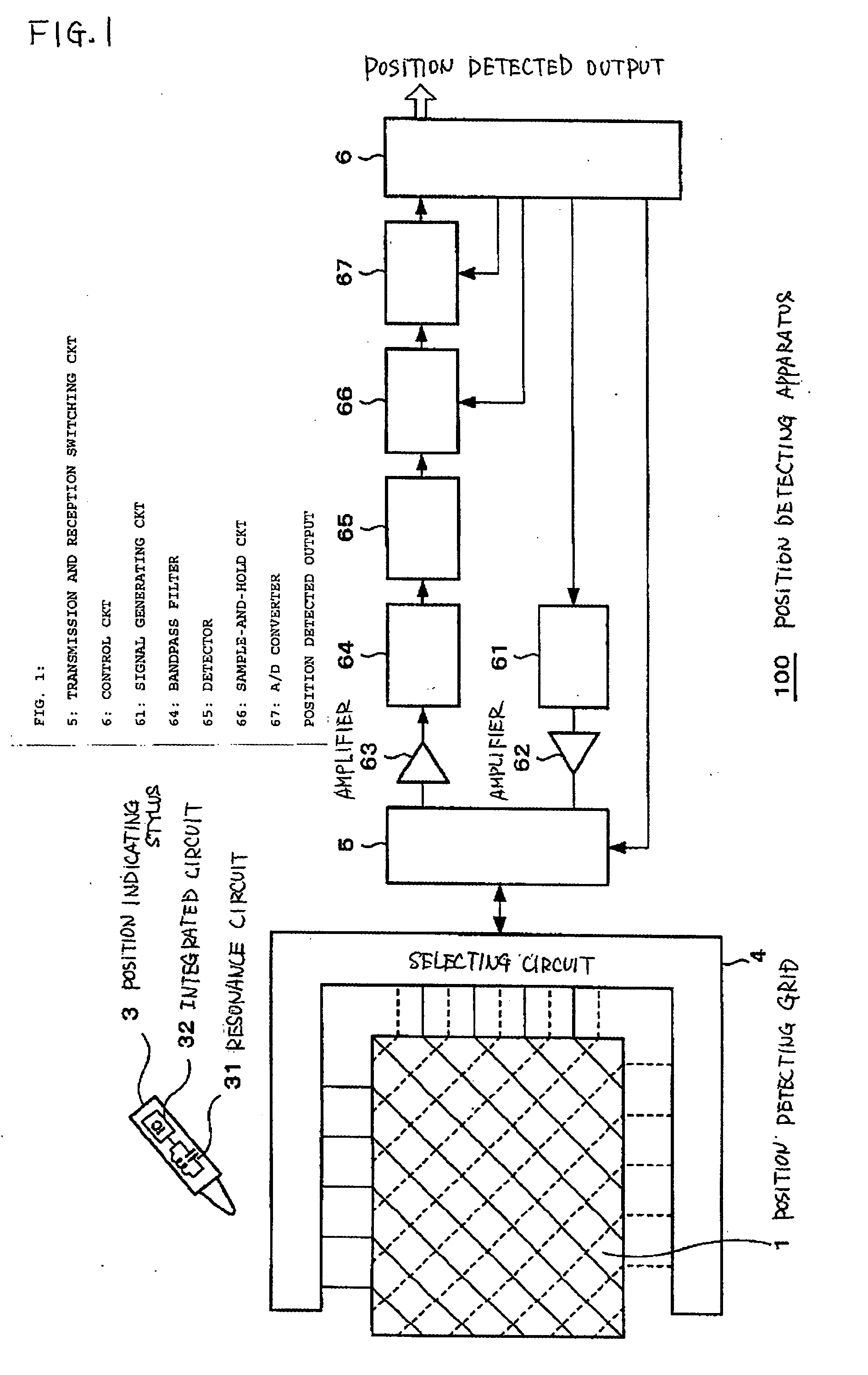
[0038]FIG. 1 illustrates a position detecting apparatus 100 according to an embodiment of the present invention.

[0039]The position detecting apparatus 100 includes a position detecting grid 1 which is schematically illustrated at a left-hand side of FIG. 1. Although a display apparatus is not illustrated in FIG. 1, it s...


PUM


Abstract

A position detecting apparatus includes a display apparatus having a screen for displaying images by changing states of a plurality of display elements arrayed in the screen along a predetermined direction which is parallel to a side boundary of the screen, and at least one detecting conductor disposed on the display apparatus to detect a position indicated on the display apparatus. The at least one detecting conductor is a loop coil having short sides and long sides, the long sides of the loop coil being arranged so as to cross the predetermined direction of the display elements.

Description

CROSS REFERENCES TO RELATED APPLICATIONS[0001]The present application claims the benefit of priority from Japanese Application No. P2006-073101 filed on Mar. 16, 2006, the disclosure of which is incorporated herein by reference in its entirety.FIELD OF THE INVENTION[0002]The present invention relates to a position detecting apparatus, a position inputting apparatus, and a computer suitable for use in directly inputting position information from a display apparatus. More specifically, the present invention relates to a position detecting apparatus, a position inputting apparatus, and a computer capable of preventing problems associated with interference patterns from being produced on a display even when a display apparatus and the position detecting apparatus are combined.BACKGROUND OF THE INVENTION[0003]A conventional position detecting apparatus provided with a display apparatus is described in Japanese Published Patent Application No. 2002-215317. The conventional position detect...

Claims


Application Information

Patent Timeline
Patent Type & Authority Applications(United States)
IPC IPC(8): G06F3/041
CPCG06F1/1616G06F1/1637G06F3/047G06F3/03545G06F3/046G06F1/1643G06F3/0412
Inventor ITO, MASAMITSU
Owner WACOM CO LTD
Learn More