Eureka AIR delivers breakthrough ideas for toughest innovation challenges, trusted by R&D personnel around the world.

Paint brush with collection reservoir

a paint brush and reservoir technology, applied in the field of handles, can solve the problems of inability to meet the ergonomic needs of users, inability to properly handle the handle of paint brushes, and inability to reduce the stress on muscles and ligaments of the hand, so as to reduce the stress on muscles and ligaments, reduce fatigue, and minimize the dripping of paint on the handle

Inactive Publication Date: 2008-09-18
STEINER MARK
View PDF8 Cites 12 Cited by
  • Summary
  • Abstract
  • Description
  • Claims
  • Application Information

AI Technical Summary

Benefits of technology

[0026]It is therefore an object of the present invention to provide a paint brush handle that will reduce hand fatigue and pressure points by use of an ergonomically designed handle as well as helps minimize the dripping of paint onto the handle. It is an object of the invention to provide a rubber surface on the handle for a more comfortable and secure grip.
[0027]It is an object of the invention to provide appropriate ergonomic contours that allow the user to grip the brush in multiple hand positions in order to help reduce hand fatigue during normal use.
[0028]It is an object of the invention to provide a rounded contour to the upper end of the handle that allows the user to grip the brush handle comfortably with their fingers in a natural grip position.

Problems solved by technology

Tile majority of common paint brush handles do not address the ergonomic needs of the user, most importantly the need to reduce pressure points and hand fatigue during prolonged use.
This pressure from the straight handle shape can result in fatigue and soreness of local hand ligaments and muscles.
The hand fatigue caused by the pressure point and prolonged use of the brush inhibits fine motor control of the hand and therefore controlled manipulation or the brush.
The flat side surfaces of a common paint brush handle can also cause strain to various hand muscles and ligaments.
When the finger tips rest on a flat surface and the fingers are forced to work on a flat plane, this finger position can cause undue strain on muscles and ligaments during the painting procedure.
Limiting the user to one hand position through the design of a set of complex surfaces on the handle will cause strain to the same hand muscles and ligaments during prolonged use.
However the overall form of the handle of this claim does not make it easy to comfortably hold the brush handle in multiple hand positions which is an important factor in reducing hand fatigue as mentioned above.
The handle contours appear clumsy with hard edges and flat sides that can cause muscle strain as mentioned above.
Although this offset feature may provide some relief at the point of contact with the hand, the small circumference of the handle can-create pressure points that can exacerbate muscle and ligament fatigue during the painting procedure.
Another problem with conventional paint brushes is the dripping of paint from the bristles onto the handle.
Prolonged use of the brush results in the excessive collection of liquids at the base of the bristles and ultimately on the handle of the brush thereby soiling the user's hands and fingers.
This solution defeats the purpose of protecting the user's hands and fingers from the paint and other liquids.
The drip lip claimed in Herron & Cox appears to be small in scale and, with the use of interchangeable brush heads, difficult to clean.
This absorbent material is removed from the brush handle and thereby exposes the user's hands and fingers to the paint or finishing liquid.
This method of application does not allow the user the option of replacing just the brush assembly or removing the brush assembly for more thorough cleaning.

Method used


Image

  • Paint brush with collection reservoir
  • Paint brush with collection reservoir
  • Paint brush with collection reservoir

Examples


Embodiment Construction

[0040]The following detailed description should be read with reference to the drawings, in which like drawings are numbered identically. The drawings depict the selected embodiment and are not intended to limit the scope of the invention. It will be understood that embodiments shown in the drawings and described below are merely for illustrative purposes, and are not intended to limit the scope of the invention as defined in the claims.

[0041]FIG. 1 is a perspective view of a handle 100 having an integrated reservoir 110 and a brush bristle assembly 200 fastened to the handle in accordance with the embodiment of the invention.

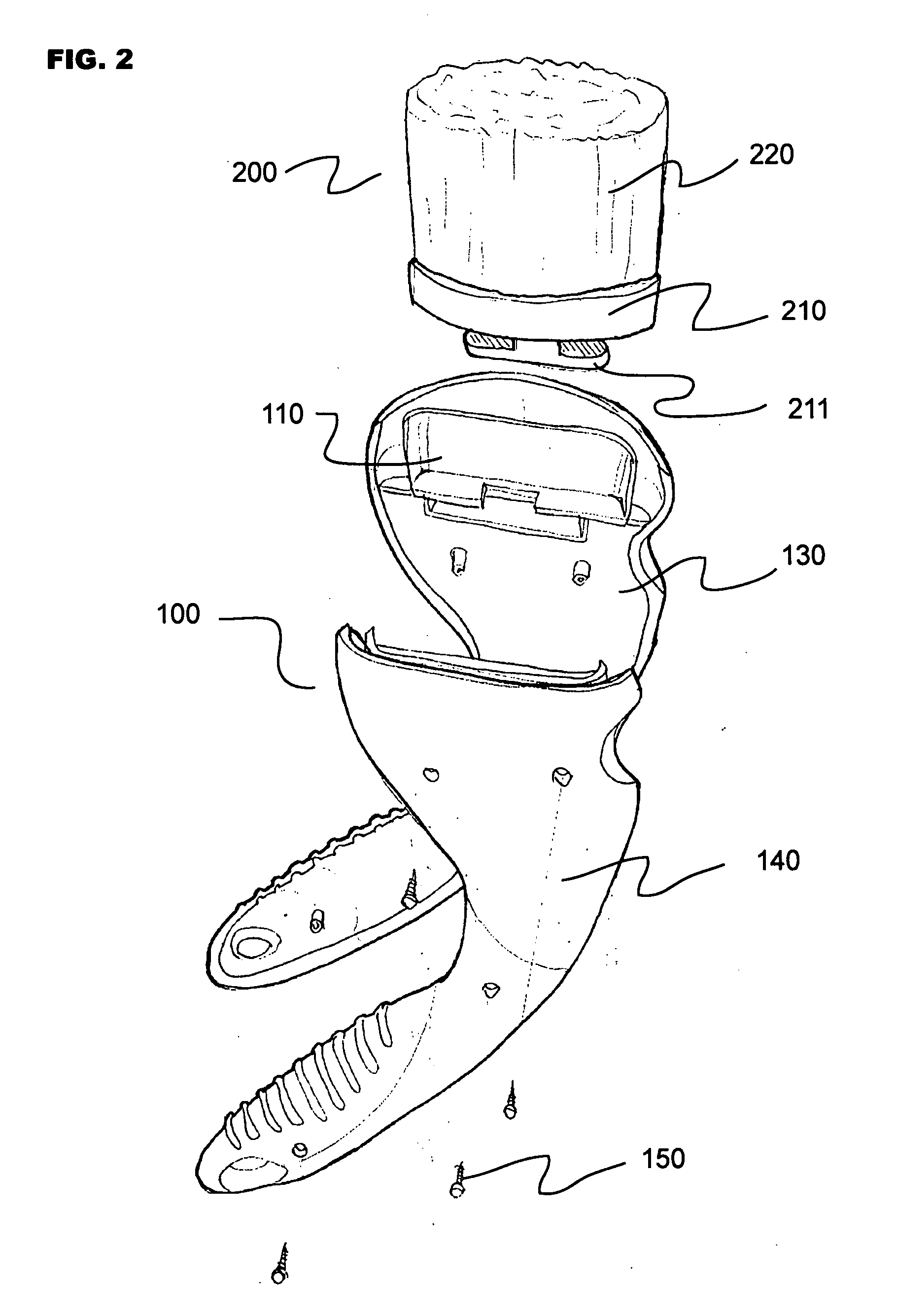
[0042]FIG. 2 is an exploded perspective view of the handle having an integrated reservoir with brush bristle assembly in accordance with an alternative embodiment of the invention. In the alternative embodiment shown, the handle 100 with integrated reservoir 110 may be formed of injection molded plastic and is a two-part design with a right half 130 and left hal...


PUM


Abstract

A paint brush handle assembly with a collection reservoir or drip cup formed as part of the handle contour with a plurality of brush bristles fixed within the handle. The collection reservoir located at the base of the brush bristles captures and collects the dripping paint, or other finishing liquids, and prevents the liquids from dripping onto the handle. The walls of the collection reservoir extend outward from the handle and surround the base of the brush bristles on all sides. The sides of the reservoir are rigid and formed as one part with the handle.

Description

BACKGROUND OF THE INVENTION[0001]The invention relates to handles; specifically ergonomically improved paint brush handles utilizing the same.[0002]Paint brushes are commonly manufactured with long straight handles made from wood or molded plastic with a metal sheath assembly containing the brush bristles fastened to the wide end of the handle. Tile majority of common paint brush handles do not address the ergonomic needs of the user, most importantly the need to reduce pressure points and hand fatigue during prolonged use.[0003]The paintbrush is manipulated by the user in several hand positions. The most common hand position is when the user places his or her fingers over the metal sheath at the base of the exposed bristles wrapping their thumb around the opposite side of the brush handle and resting it against the opposite side of tile sheath. When gripping the handle in this manner, the straight elongated handle creates a pressure point in the crotch of the hand between the thumb...

Claims


Application Information

Patent Timeline
IPC IPC(8): A46B5/00
CPCA46B11/00A46B2200/202A46B15/0002
Inventor STEINER, MARK
Owner STEINER MARK
Why Eureka
Eureka Blog
Learn More