
Machine with automated steering system

a technology of automatic steering and machine, which is applied in the direction of process control, navigation instruments, instruments, etc., can solve the problems of difficult to accomplish, difficult for the operator to simultaneously accomplish all the tasks necessary for finely grading a complex work si

Active Publication Date: 2008-08-28
CATERPILLAR INC
View PDF23 Cites 59 Cited by
  • Summary
  • Abstract
  • Description
  • Claims
  • Application Information

AI Technical Summary

Problems solved by technology

Positioning the blade of a motor grader is a complex and time-consuming task and is difficult to do when making complicated cuts or contouring surfaces, and to do so while also steering the grader.
Because grading tasks are complicated and time-consuming, it is difficult for the operator to simultaneously accomplish all of the tasks necessary for finely grading a complex work site.
The operator must control machine trajectory, the complexity of which may increase with increasing numbers of passes and turns.
The difficulty of such operations may reduce the productivity and efficiency of the operator.
Because the Grey system relies on pre-made maps, the number and variety of work sites open to automatic steering may be limited by the inventory of maps.
In addition, the storage of such pre-made maps can require additional memory, adding to the cost of the system.
Additionally, the system in the Gray patent offers only one possible path based on the least number of passes required to traverse the work site.
If the path is designed based on the minimal number of passes, it might be suboptimal because it may originate at an undesired point.
Furthermore, it might be impossible to fully sculpt the work site along a particular path because of obstructions omitted from the stored map.
Furthermore, the system in Gray fails to ensure that the motor grader is placed within the vicinity of the initial position and orientation suggested by the path.
Any deviation from the path caused by the misalignment may cause errors in the grading.
Such generated errors may require corresponding corrections leading to decreased efficiency and increased construction costs.

Method used


Image

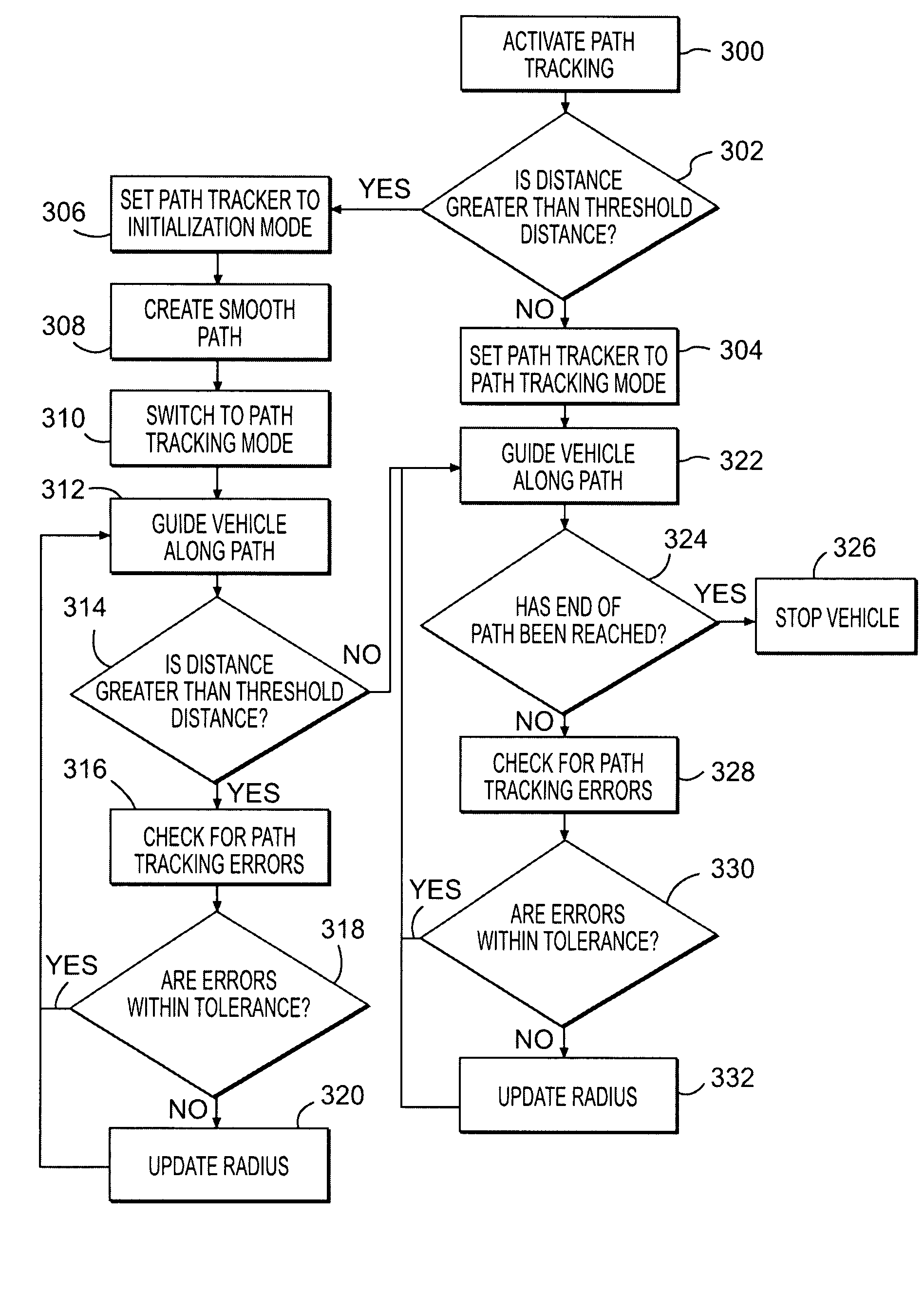
  • Machine with automated steering system
  • Machine with automated steering system
  • Machine with automated steering system

Examples


Embodiment Construction

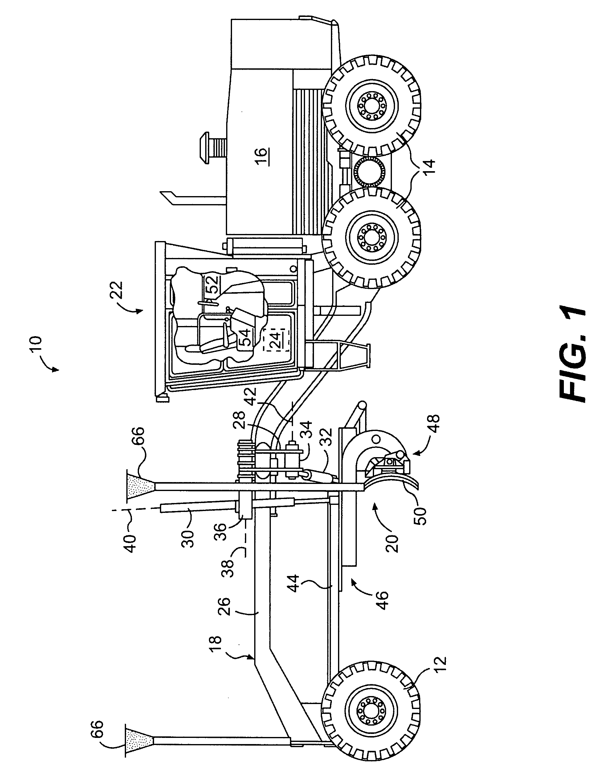
[0021]An exemplary embodiment of a machine 10 is illustrated in FIG. 1. Machine 10 may be a motor grader, a backhoe loader, an agricultural tractor, a wheel loader, a skid-steer loader, or any other type of machine known in the art. Machine 10 may include a steerable traction device 12, a driven traction device 14, a power source 16 supported by driven traction device 14, and a frame 18 connecting steerable traction device 12 to driven traction device 14. Machine 10 may also include a work implement such as, for example, a drawbar-circle-moldboard assembly (DCM) 20, an operator station 22, and a control system 24.

[0022]Both steerable and driven traction devices 12, 14 may include one or more wheels located on each side of machine 10 (only one side shown). The wheels may be rotatable and / or tiltable for use during steering and leveling of a work surface (not shown). Alternatively, steerable and / or driven traction devices 12, 14 may include tracks, belts, or other traction devices kno...


PUM


Abstract

A system is provided for regulating a travel course of a machine. The system has a steering system operationally connected to at least one ground engaging device. Additionally, the system has a path generator configured to generate a path along which the machine can travel. The system also has a path tracker configured to automatically regulate the steering system to position the machine within a predetermined vicinity of an initial point on the generated path and guide the machine along the generated path.

Description

TECHNICAL FIELD[0001]The present disclosure is directed to a machine having a steering system, and more particularly, to an automated steering system capable of generating a travel path for the machine.BACKGROUND [0002]Motor graders are used primarily as a finishing tool to sculpt a surface of a construction site to a final shape and contour. Typically, motor graders include many hand-operated controls to steer the wheels of the grader, position a blade, and articulate the front frame of the grader. The blade is adjustably mounted to the front frame to move relatively small quantities of earth from side to side. The articulation angle is adjusted by rotating the front frame of the grader relative to the rear frame of the grader.[0003]While preparing the subsurface of, for example, a parking lot, highway, or golf course, it is desirable to ensure the accuracy of the boundary and contour of the work area. A motor grader may make multiple passes back and forth across the work area in o...

Claims


Application Information

Patent Timeline
IPC IPC(8): G01C21/32
CPCG01C21/32G05D2201/0202G05D1/0278G05D1/0274
Inventor GHARSALLI, IMEDBHASKAR, VIVEK
Owner CATERPILLAR INC
Learn More