
Process and system used to discover and exploit the illusory depth properties inherent in an autostereoscopic image

a technology of autostereoscopic image and depth properties, applied in the field of process and system used to discover and exploit the depth properties inherent in autostereoscopic image, can solve the problems of visual components appearing stuttered, jagged or otherwise dispersed, and achieve optimal autostereoscopic properties, optimize the perceived autostereoscopic effect, and maximize the effect of the perceived

Inactive Publication Date: 2008-08-28
BODINET JOSHUA
View PDF8 Cites 4 Cited by
  • Summary
  • Abstract
  • Description
  • Claims
  • Application Information

AI Technical Summary

Benefits of technology

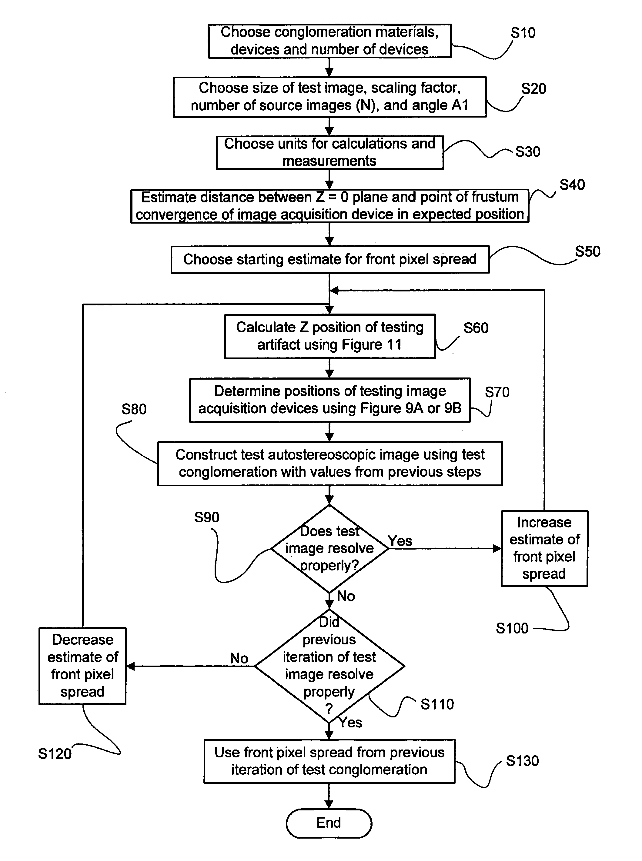
[0032]One aspect of the invention is, thus, a method for setting up an arrangement of objects and image acquisition devices in order to acquire a set of photographs, or computer generated images, to be used in the testing of the autostereoscopic properties of a combination of materials etc. to be used to produce an autostereoscopic image. The autostereoscopic image produced from this test is examined to determine parameters to be used in image acquisition device positioning which will yield good-quality / maximized results in practical situations.
[0035]The present invention provides for two metrics, the front pixel spread and the back pixel spread, which allow for precise image acquisition positioning in circumstances physically and conceptually far removed from the conglomeration being used to generate the resultant autostereoscopic image, as well as an ergonomically-friendly process by which values for these two metrics are determined. Features of the present invention provide for image acquisition either occurring in the real world (via digital or analog means) or within a computer graphic environment (or a blend of both), by way of specific methods necessary for successfully traveling through a variety of different mathematical spaces to arrive at a common space. Finally, the present invention provides a variety of methods by which image acquisition device positioning is able to be computed, a class of which allows for greater accuracy.

Problems solved by technology

Autostereoscopic images created without proper attention to these factors can result in the visual components appearing stuttered, jagged or otherwise dissipated.

Method used


Image

  • Process and system used to discover and exploit the illusory depth properties inherent in an autostereoscopic image
  • Process and system used to discover and exploit the illusory depth properties inherent in an autostereoscopic image
  • Process and system used to discover and exploit the illusory depth properties inherent in an autostereoscopic image

Examples


Embodiment Construction

[0066]As mentioned previously, one of the objects of the present invention is to provide a method of systematically determining certain parameters for the creation of an autostereoscopic image, so that the illusory three-dimensional space created in the image is optimized. In the preferred embodiment, the method includes two main phases—a Discovery Phase and an Exploitation Phase. During the Discovery Phase, as explained in more detail below, certain parameters are determined using a test image. In the Exploitation Phase, the parameters determined are utilized in creating the desired autostereoscopic image.

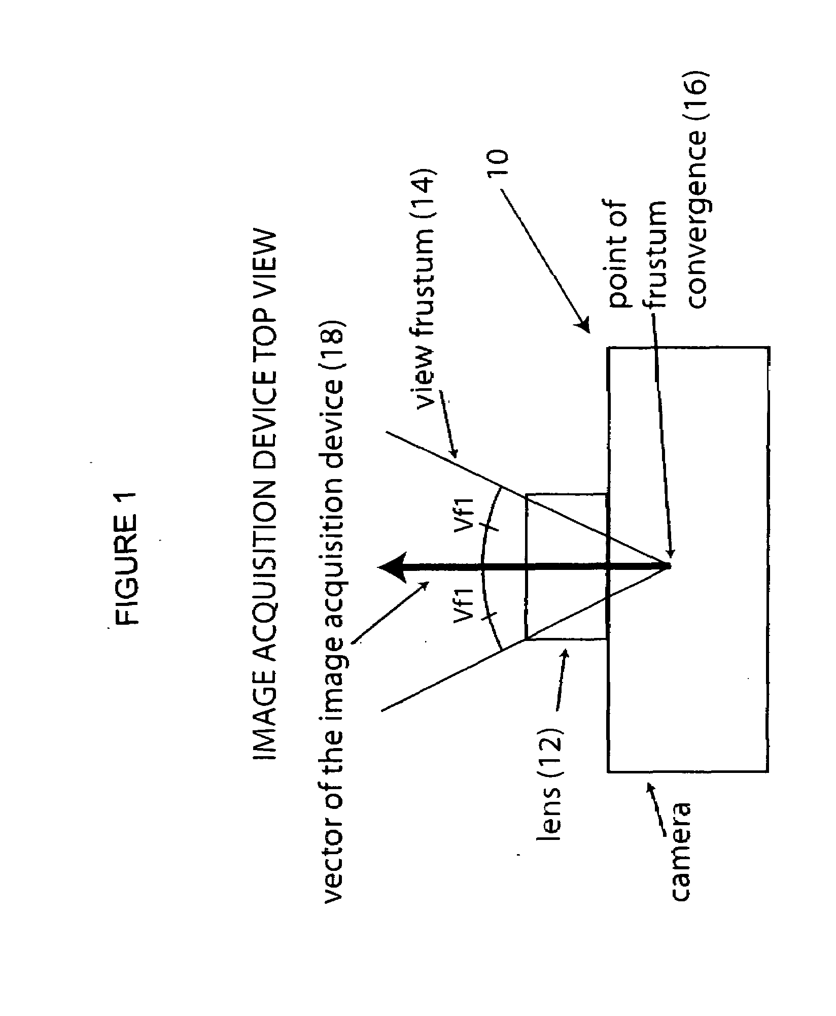
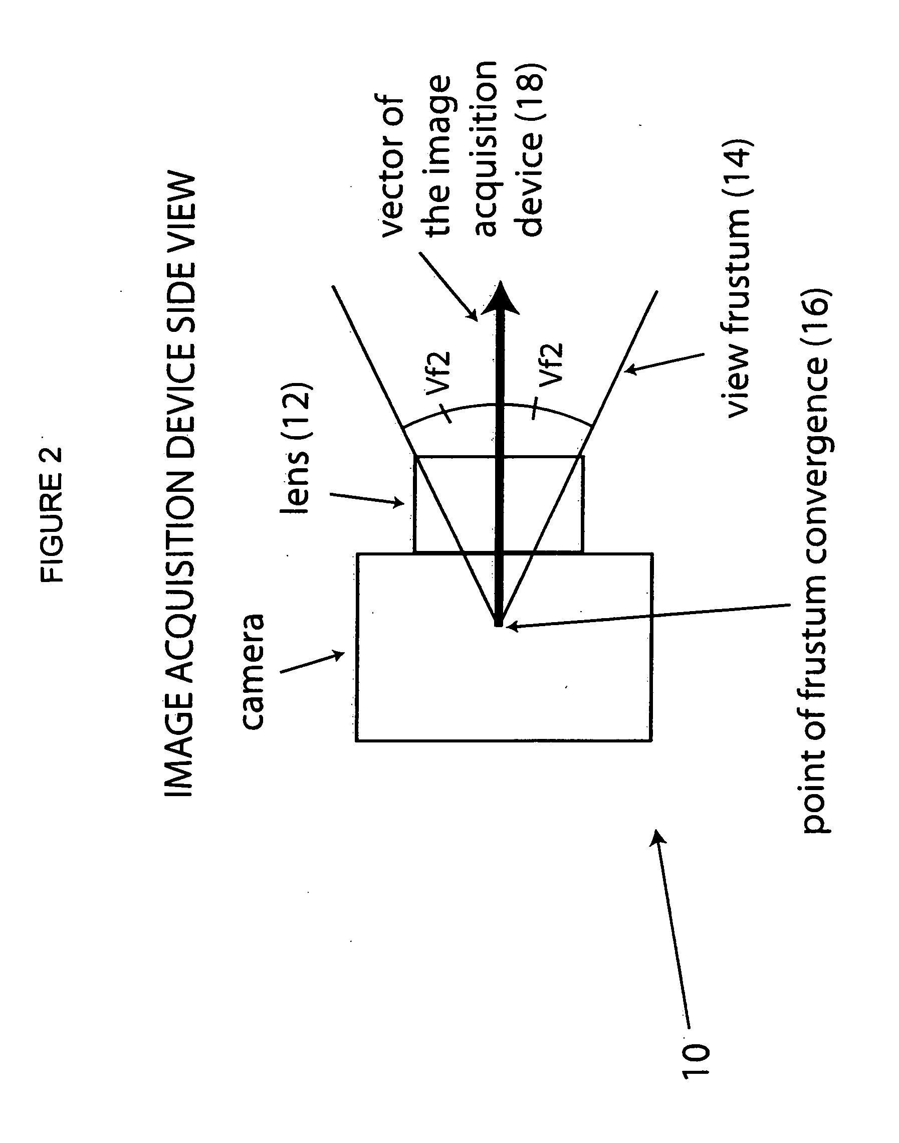
[0067]Prior to beginning the explanation of the Discovery Phase and the Exploitation Phase, certain features of image acquisition devices and autostereoscopic images will be discussed. Turning now to FIGS. 1 and 2, these figures schematically show a top view (FIG. 1) and a side view (FIG. 2) of an image acquisition device 10. Image acquisition device 10 may be an actual camera of ...


PUM


Abstract

A method, system and devices for optimizing and / or maximizing the perceived autostereoscopic effect for any chosen combination of photographic or electronic recording materials, recording methods and parameters, and imaging methods and parameters. The method first determines the parameters characterizing the optimum autostereoscopic effect of the combination materials etc. (the front pixel spread and the back pixel spread), then specifies how to apply these parameters to the arrangement of image acquisition devices, or the production of images by computational means, to produce a final image with optimal autostereoscopic properties. Features of the present invention provide for image acquisition either occurring in the real world (via digital or analog means) or within a computer graphic environment (or a blend of both), by way of specific methods necessary for successfully traveling through a variety of different mathematical spaces to arrive at a common space.

Description

[0001]The present invention relates generally to method used to determine the parameters necessary for increasing the perceived three-dimensional effect of an autostereoscopic image, and to a method of using those parameters, as well as to a system, or systems, of components for implementing the methods. More particularly, the present invention relates to a Discovery Phase, in which certain parameters for increasing the autostereoscopic effect are determined; an Exploitation Phase, in which those parameters determined in the discovery phase are used with image acquisition devices to create an autostereoscopic image; and to one or more systems of components for implementing the Discovery Phase and / or the Exploitation Phase.[0002]Throughout this Specification, numerous terms of art will be used. In order to aid the reader with the understanding of this invention, the following definitions are provided (terms not defined below, or elsewhere in this Specification, should be considered a...

Claims


Application Information

Patent Timeline
IPC IPC(8): H04N13/04
CPCH04N13/0404H04N13/0425H04N13/0409H04N13/305H04N13/31H04N13/327
Inventor BODINET, JOSHUA
Owner BODINET JOSHUA
Learn More