
Modular aircraft interior configuration and methods

Active Publication Date: 2008-07-31
EMBRAER SA
View PDF22 Cites 9 Cited by
  • Summary
  • Abstract
  • Description
  • Claims
  • Application Information

AI Technical Summary

Benefits of technology

[0004]Larger executive jets typically allow more customized configurations, but structural rework is required in order to provide the necessary attachment points. Modules, in this case, are not clearly defined as monument and / or seat arrangements designed to be installed in a marked zone of the aircraft. Especially in the Executive Jets market, the possibility of floor plan customization is a very important requirement for the customer. A modular interior configuration greatly improves the possibility of customization since different aircraft interior fixtures can be arranged on the same position inside a defined zone.
[0006]It would therefore be desirable if aircraft interior fixture arrangement could be provided having greater universal orientation capabilities which in turn could provide for greater flexibility of fixture placements within the aircraft interior to achieve different configurations. It is towards fulfilling such needs that the present invention is directed.
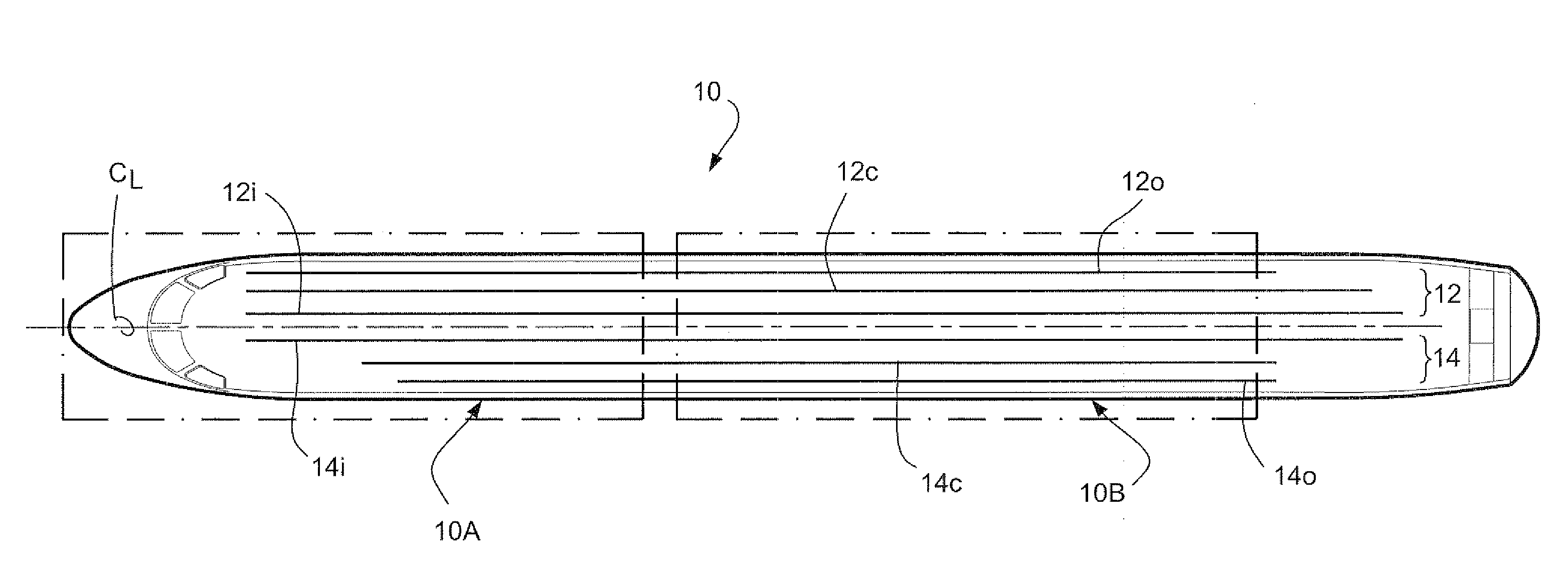
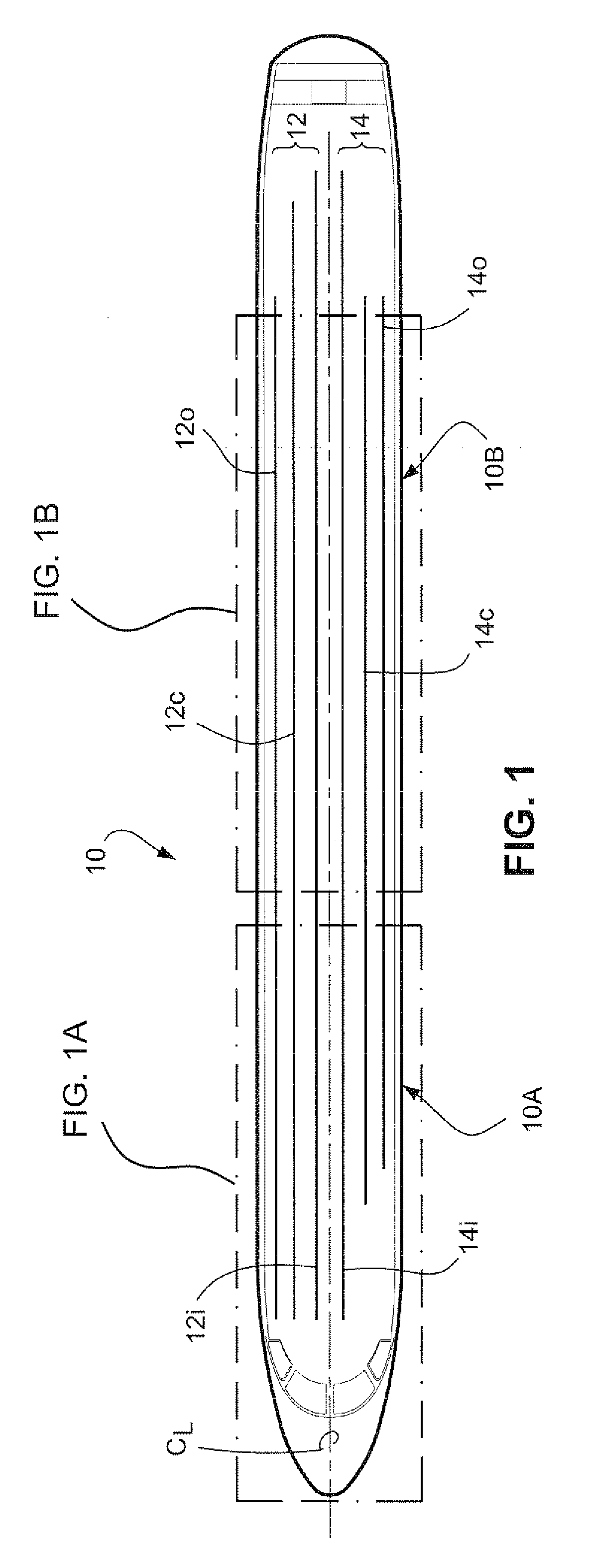
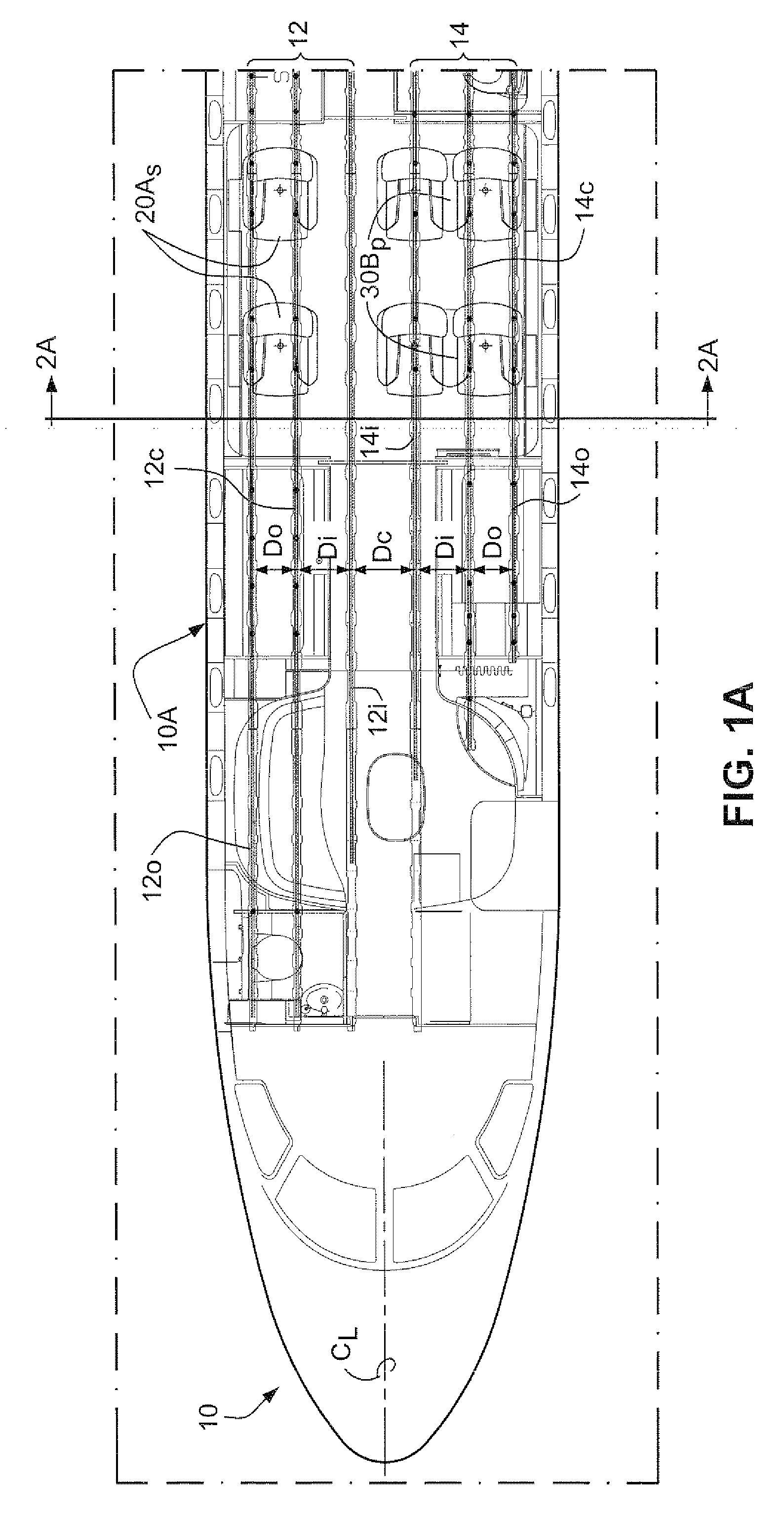
[0007]Broadly, embodiments of the present invention generally provide for a modular configuration for the aircraft interior floor plan design. The modular configuration allows a higher level of interior customization for the owner, who can choose between a number of pre-defined aircraft interior fixture arrangements inside a limited zone of the aircraft. These zones have structural provisions that allow the installation of the different interior fixtures on different positions inside the aircraft fuselage.

Problems solved by technology

Passenger interior floor plans conventionally allow a limited degree of customization if little structural rework is desired.
Flexible interior fixture placement within an aircraft becomes problematic for aircraft having symmetrically arranged pairs of longitudinal attachment tracks, wherein the tracks are separated by unequal dimensions.

Method used


Image

  • Modular aircraft interior configuration and methods
  • Modular aircraft interior configuration and methods
  • Modular aircraft interior configuration and methods

Examples


Embodiment Construction

[0020]As used herein and in the accompanying claims, various terms of orientation are used in relation to an aircraft and have the following definitions. The terms “forward” and “aft” directionally mean towards the forward and aft portions, respectively, of an aircraft's fuselage as viewed in a forward facing position. Similarly, “starboard” and “port” directionally mean the right and left sides, respectively, of an aircraft as viewed in a forward facing position relative to the fuselage centerline of the aircraft. The terms “inboard” and “outboard” mean a direction toward and away from, respectively, the fuselage centerline of the aircraft. The term “longitudinal centerline plane” when referring to an aircraft interior fixture means a plane which bisects the aircraft fixture longitudinally parallel to the longitudinal centerline plane of the aircraft fuselage.

[0021]Accompanying FIGS. 1A and 1B represent forward and aft fuselage sections 10A, 10B of an aircraft 10 showing a possible...


PUM


Abstract

Modular configuration for an aircraft interior floor plan design is provided by an fuselage having starboard and port side attachment rails disposed longitudinally parallel to one another. Each of the starboard and port side attachment rails are comprised of outboard and inboard rails and a center rail positioned therebetween. A plurality of interior fixtures are provided with fixed attachment posts asymmetrically oriented relative to a longitudinal centerline plane of the fixture. Such fixtures can therefore be attached to predetermined pairs of the starboard and port side attachment rails to provide for a desired configuration of the fixtures within the fuselage.

Description

CROSS-REFERENCE TO RELATED APPLICATION[0001]This application is related to and claims domestic priority benefits under 35 USC §119(e) from U.S. Provisional Application Ser. No. 60 / 897,493 filed on Jan. 26, 2007, the entire content of which is expressly incorporated hereinto by reference.FIELD OF THE INVENTION[0002]This invention relates generally to aircraft and, more specifically, to passenger aircraft interior configurations and methods. In especially preferred embodiments, the present invention relates to aircraft interior fixtures (e.g., single and dual passenger seat assemblies, tables, sofas and the like) which may be positioned within the aircraft interior at various locations to achieve desired interior configurations.BACKGROUND AND SUMMARY OF THE INVENTION[0003]Passenger interior floor plans conventionally allow a limited degree of customization if little structural rework is desired. Usually aircraft interior fixtures can be installed for smaller executive jets on areas de...

Claims


Application Information

Patent Timeline
IPC IPC(8): B64D11/00B64D11/06
CPCB64D11/00B64D11/0601B64D11/06B64D11/0696
Inventor DE SIQUEIRA, FERNANDO ANTONIO PONZO
Owner EMBRAER SA
Learn More