Eureka AIR delivers breakthrough ideas for toughest innovation challenges, trusted by R&D personnel around the world.

Load balancing for complex database query plans

a database and load balance technology, applied in the field of database, can solve the problems of not addressing the problem of how and it is difficult to generate parallel query plans that make effective use of multiple processors or disks

Active Publication Date: 2008-06-19
IANYWHERE SOLUTIONS
View PDF11 Cites 74 Cited by
  • Summary
  • Abstract
  • Description
  • Claims
  • Application Information

AI Technical Summary

Benefits of technology

[0008]Methods, systems, and apparatuses for generating complex parallel query plans with load balancing characteristics are provided. Database query plans are trees of opera

Problems solved by technology

It does not address the issue of how to generate parallel query plans for particular queries.
Given a query and a set of parallel operators, it is difficult to generate a parallel query plan that makes effective use of multiple processors or disks.
One difficulty with constructing parallel query plans is arranging for all available processors to remain busy throughout the execution of the query.

Method used


Image

  • Load balancing for complex database query plans
  • Load balancing for complex database query plans
  • Load balancing for complex database query plans

Examples


example database

Query Algorithms and Operators

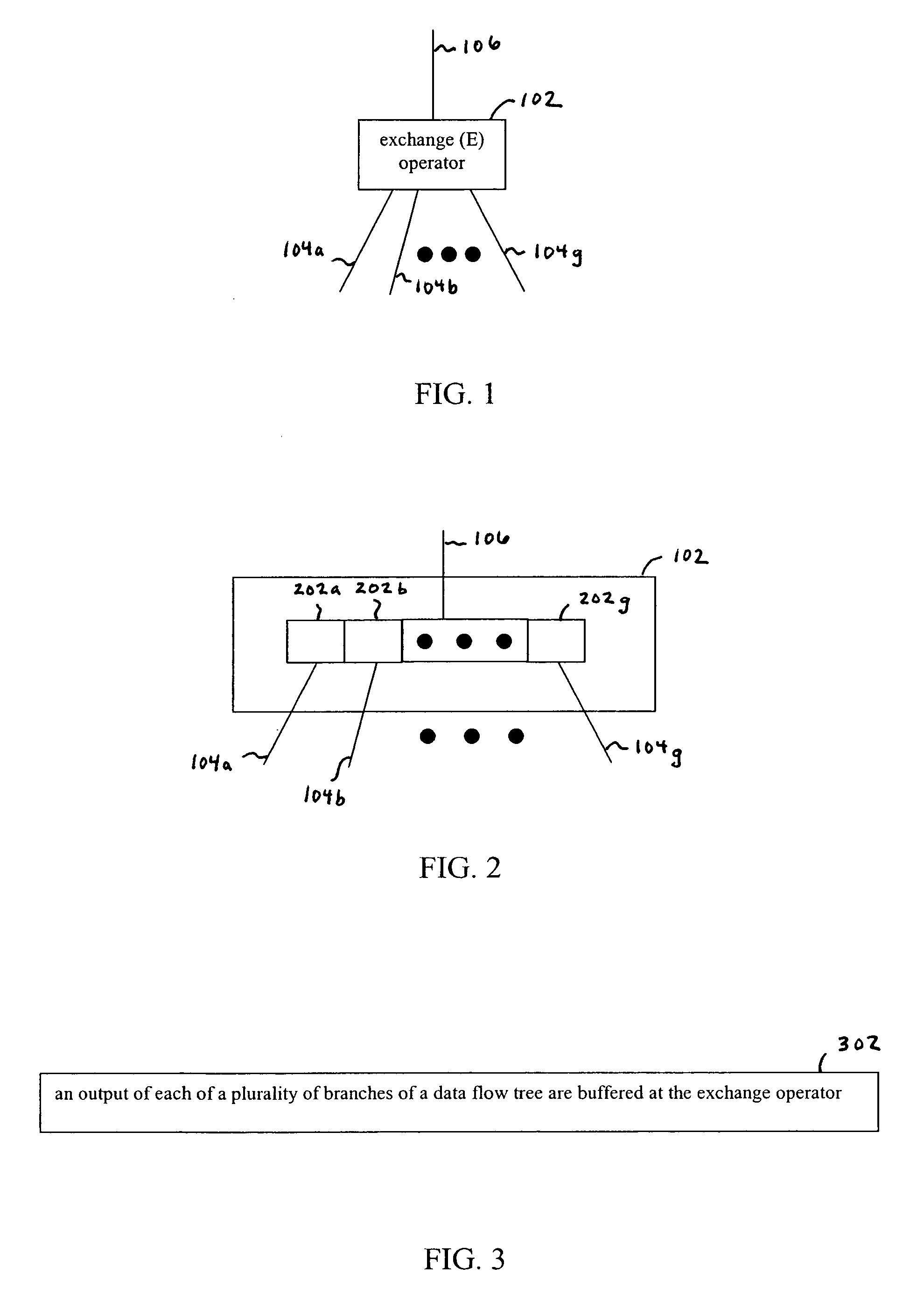
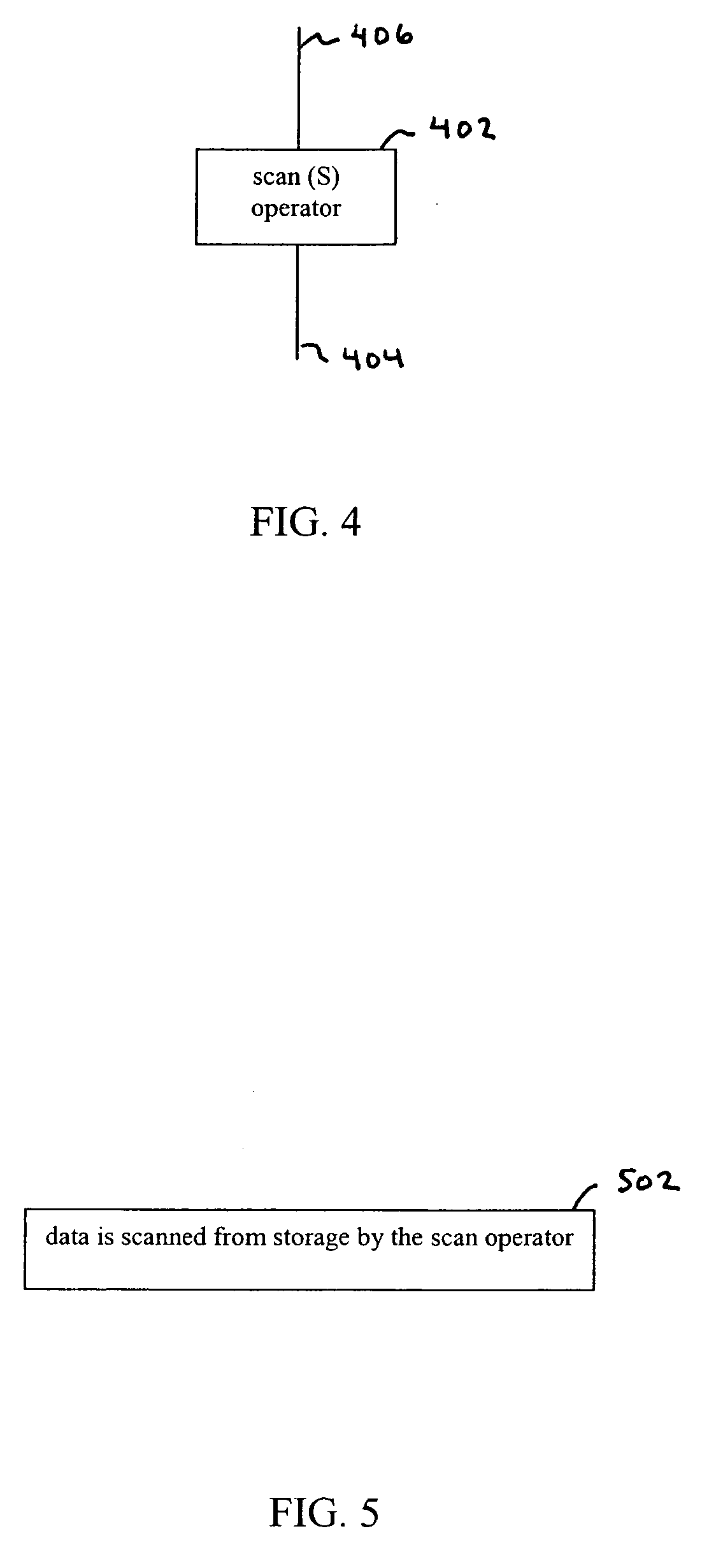
[0043]Database query algorithms include the use of data flow operators. A particular database query plan is organized as a tree of such operators. Each operator implements a different physical algorithm. Example operators include “hash join,”“hash group by,” and “table scan.” Typically, each operator has the same interface: open, next, and close. Because each operator has the same interface, an operator in a node of a tree does not need to know anything about the operators located at its parent or child nodes. Many such operators are known to persons skilled in the relevant art(s). Several well known operators are described below for illustrative purposes. For purposes of brevity, further data flow operators are not described. The data flow operators described below, and further data flow operators that would be known to persons skilled in the relevant art(s), are applicable to being parallelized according to embodiments of the present invention. The op...

example computer implementation

[0119]In an embodiment of the present invention, the system and components of the present invention described herein are implemented using well known servers / computers, such as computer 3302 shown in FIG. 33. For example, computer system 114 and server 116 shown in FIG. 1 can be implemented using computers 3302.

[0120]The computer 3302 can be any commercially available and well known computer capable of performing the functions described herein, such as computers available from International Business Machines, Apple, Sun, HP, Dell, Compaq, Digital, Cray, etc.

[0121]The computer 3302 includes one or more processors (also called central processing units, or CPUs), such as a processor 3306. The processor 3306 is connected to a communication bus 3304. In some embodiments, processor 3306 can simultaneously operate multiple computing threads.

[0122]The computer 3302 also includes a main or primary memory 3308, such as random access memory (RAM). The primary memory 3308 has stored therein con...


PUM


Abstract

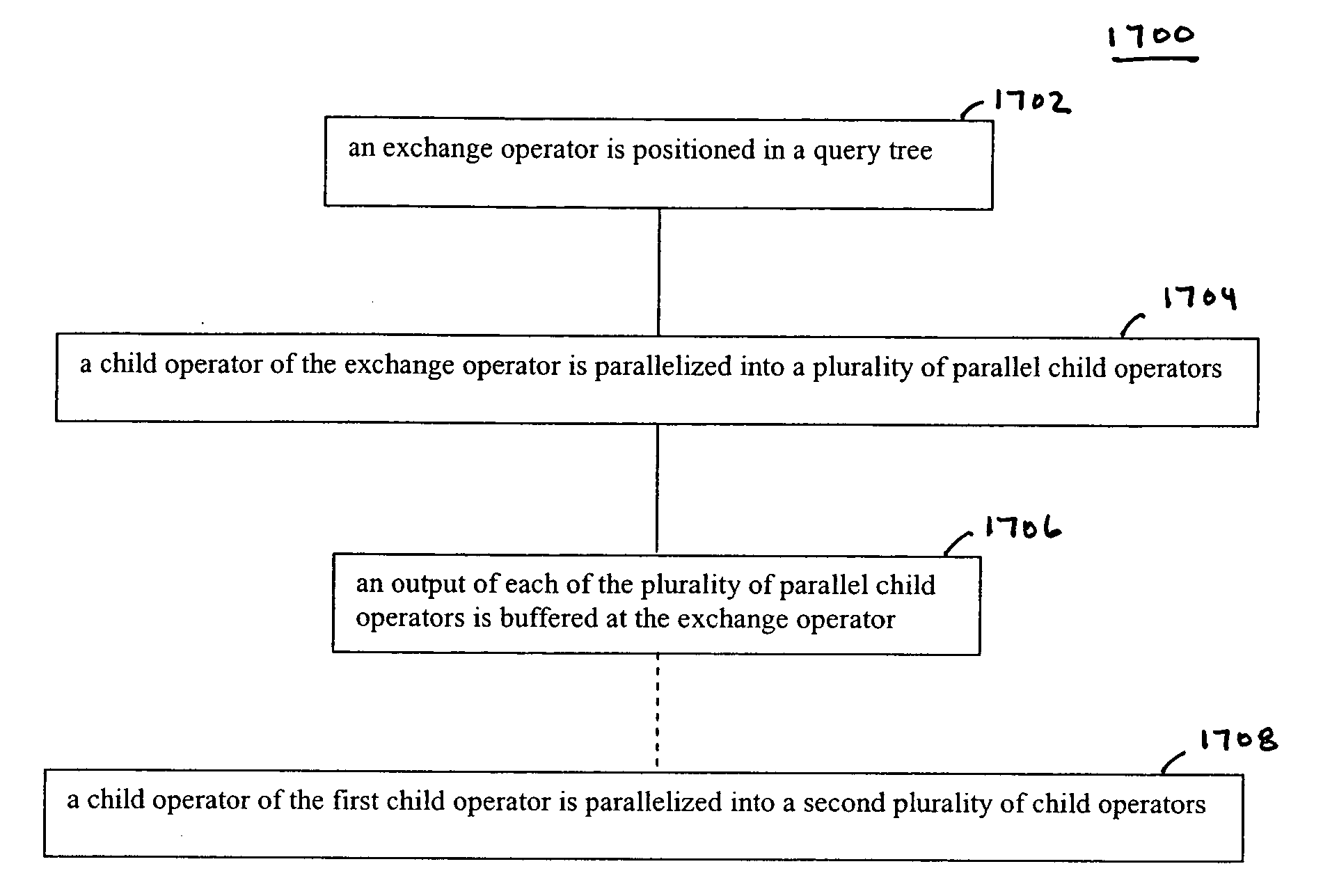
Methods, systems, and apparatuses for improving performance of parallel database query plans are described. An exchange operator is positioned in a query tree. A child operator of the exchange operator is parallelized into a plurality of parallel child operators, each of the parallel child operators coupled to the exchange operator in a respective branch of a plurality of parallel branches of the query tree. An output of each of the plurality of parallel child operators may be buffered at the exchange operator. Furthermore, child operators of the plurality of parallel child operators may also be parallelized. Query plans of any form and containing any number of operators may be parallelized in this manner. Any number of parallel branches may be used, independent of the number of operators in the original plan. The parallelized query plans achieve effective load balancing across all branches.

Description

BACKGROUND OF THE INVENTION[0001]1. Field of the Invention[0002]The present invention relates to databases, and more particularly, to algorithms for more efficiently processing database queries using parallelism.[0003]2. Background Art[0004]Parallel database systems improve query performance by using multiple processors and storage devices. They choose and execute query plans specially constructed to utilize parallel resources. For example, the “volcano” query processing system uses various data flow operators in query plans that are organized as trees. See Graefe, Goetz, “Encapsulation of Parallelism in the Volcano Query Processing System,” SIGMOD Conference (1990), pp. 102-111. Each operator in a volcano query tree has the same interface. Thus, an operator in a node of a tree does not need to know anything about its parent or child nodes. Parallel plans in volcano are simply trees that contain special parallel operators. The “exchange” operator is one example. It acts as a boundar...

Claims


Application Information

Patent Timeline
IPC IPC(8): G06F7/06
CPCG06F17/30445G06F16/24532
Inventor YOUNG-LAI, MATTHEW
Owner IANYWHERE SOLUTIONS
Why Eureka
Eureka Blog
Learn More