Eureka AIR delivers breakthrough ideas for toughest innovation challenges, trusted by R&D personnel around the world.

System For Reducing Feedback Noise Due to Relaxation Oscillation in Optical Data Recording Reproducing Systems Using Optimized External Cavity

a technology of optical data recording and reproducing system, applied in the field of system and a method for reducing feedback noise in an optical data recording/reproducing system, can solve the problems of limited noise and laser noise in relation, and achieve the effect of reducing laser noise due to feedback light, reducing feedback noise, and high output level

Inactive Publication Date: 2008-06-19
KONINKLIJKE PHILIPS ELECTRONICS NV
View PDF3 Cites 2 Cited by
  • Summary
  • Abstract
  • Description
  • Claims
  • Application Information

AI Technical Summary

Benefits of technology

The present invention provides a method and system for reducing feedback noise in optical data recording / reproducing systems. This is achieved by determining the relaxation oscillation frequency of the pulsating light emitted from the laser and adjusting the optical length accordingly. The current used to drive the laser can be an alternating current or a direct current, and the system can include a series of optical output pulses. The technical effects of this invention include reduced laser noise, improved reduction of noise generated by feedback light, and improved performance of optical data recording / reproducing systems.

Problems solved by technology

In particular, in the design of the disclosed system a relationship between the disc surface reflection and NL is considered so that even when reflections occur the resulting noise is limited by designing the optical length appropriately.
None of the above patents or patent application, however, describe laser noise in relation to relaxation oscillation frequency, which is an intrinsic property of the laser.

Method used


Image

  • System For Reducing Feedback Noise Due to Relaxation Oscillation in Optical Data Recording Reproducing Systems Using Optimized External Cavity
  • System For Reducing Feedback Noise Due to Relaxation Oscillation in Optical Data Recording Reproducing Systems Using Optimized External Cavity
  • System For Reducing Feedback Noise Due to Relaxation Oscillation in Optical Data Recording Reproducing Systems Using Optimized External Cavity

Examples


Embodiment Construction

[0024]In the following description of the various embodiments, reference is made to the accompanying figures, which are shown by way of illustration in which the invention may be practiced. It is to be understood that other embodiments may be utilized and structural and functional modifications may be made without departing from the scope of the present invention.

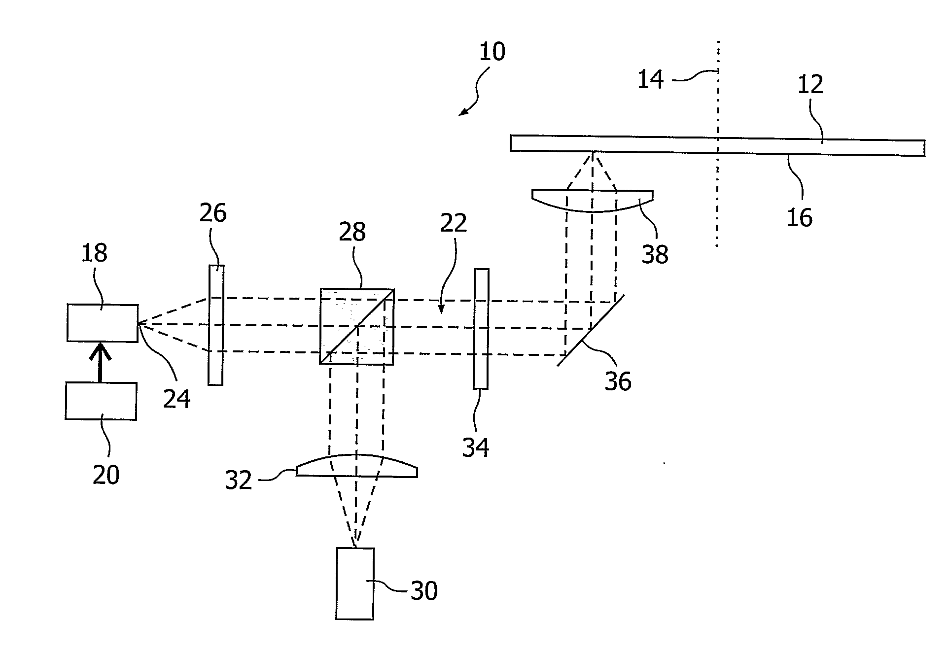
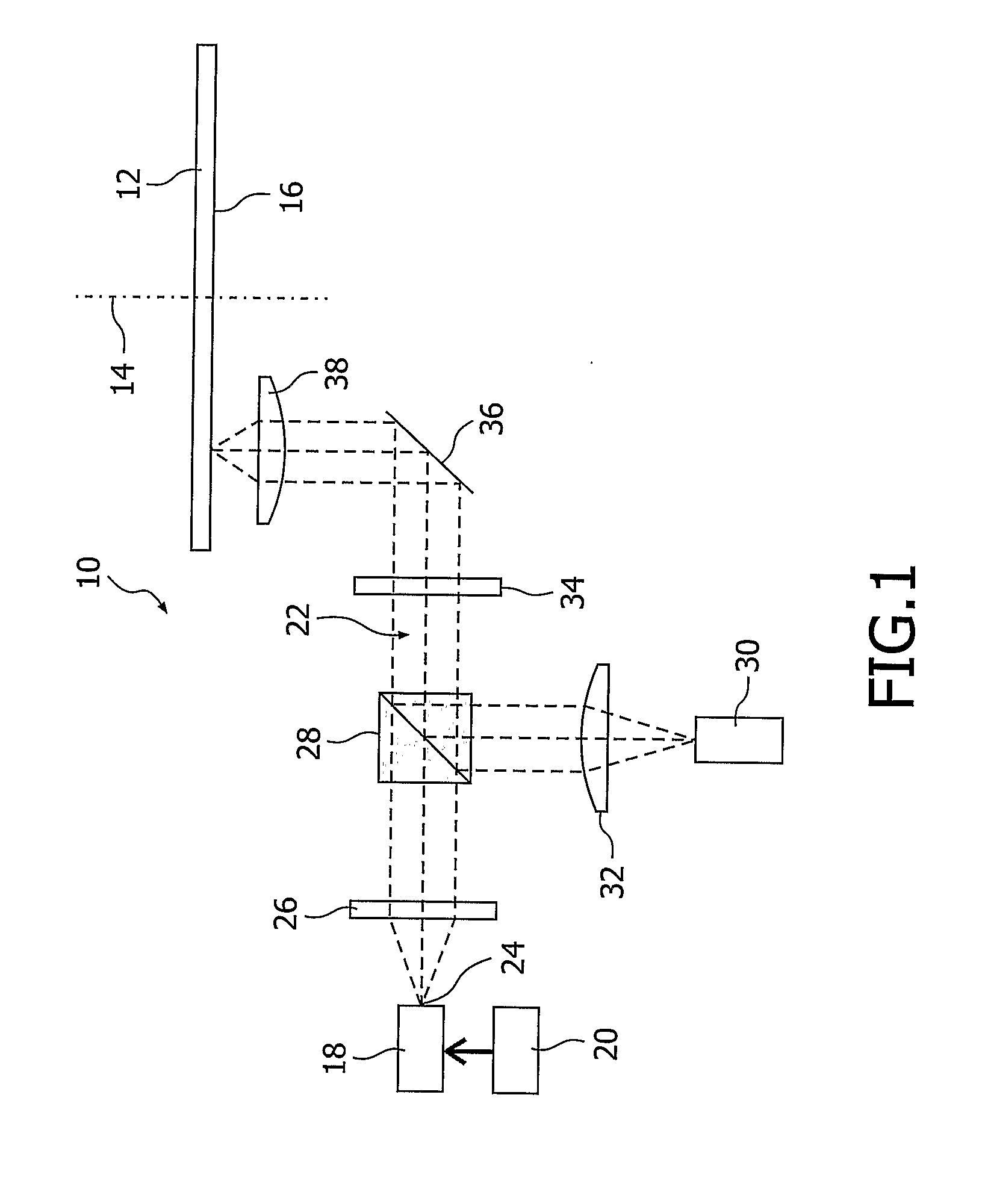
[0025]FIG. 1 shows a system 10 for recording / reproducing optical data from an optical storage medium 12. The optical storage medium 12 may comprise any type of optical, electro-optical, or magneto-optical storage capabilities, such as a CD, DVD, Blu-Ray Disc, MD or Mos. The optical storage medium 12 is shown in FIG. 1 with a symmetry line 14 about which the storage medium 12 may rotate so as to enable access to every part of the surface 16 of the storage medium 12.

[0026]The system 10 comprises a laser 18 driven by an AC and a DC current generated by a laser exciter 20 so as to generate a pulsating light 22 emitting from the...


PUM

PropertyMeasurementUnit
optical lengthaaaaaaaaaa
relaxation oscillation frequencyaaaaaaaaaa
speedaaaaaaaaaa

Abstract

This invention relates to a method for reducing feedback noise in an optical recording / reproducing system (10) comprising a laser (18) driven by an AC and a DC current thereby generating a pulsating light (22) emitted from said laser (18) to an external cavity defining an optical length (L) from said laser (18) to an optical storage medium (12), such as a compact disc (CD), digital versatile disc (DVD), Blu-Ray Disc, MiniDisc (MD), or magnetooptic disc (MOD). The optical length (L) is adjusted in accordance with the relaxation oscillation frequency.

Description

FIELD OF INVENTION [0001]This invention relates to a system and a method for reducing feedback noise in an optical data recording / reproducing system such as a compact disc (CD), digital versatile disc (DVD), or Blu-Ray Discs (BD) an optical disc standard based on the use of a blue laser rather than red laser as used for DVDs, and such as a photo-electromagnetic disc i.e. MiniDisc (MD), or magnetooptical disc (MOD). In particular, this invention relates to the use of optimized radio-frequency modulation for reducing feedback noise.BACKGROUND OF INVENTION [0002]European patent application No. EP 0 887 898 discloses a system for providing countermeasures against laser noise (optical feedback noise) by way of optimizing a relationship between the optical length between the laser device and the recording medium (external resonator length) and internal resonator length (L) of a semiconductor laser times effective reflective index (N) of the semiconductor laser. In particular, in the desig...

Claims


Application Information

Patent Timeline
Patent Type & Authority Applications(United States)
IPC IPC(8): G11B7/125H01S5/0683H01S3/13H01S5/062H01S5/065H01S5/10
CPCG11B7/126H01S5/06216H01S2301/02H01S5/0658H01S5/0656H01S5/0683
Inventor 'T HOOFT, GERT WIMSCHLEIPEN, JOHANNES JOSEPHUS HUBERTINA BARBARAVAN DE NES, ARTHUR SIEWERT
Owner KONINKLIJKE PHILIPS ELECTRONICS NV
Why Eureka
Eureka Blog
Learn More