Image processing apparatus, image processing method, and program
a color image and image processing technology, applied in the field of color image reduction, can solve the problems of inability to obtain proper, deconvolution and approximate edge enhancement processing, and it is difficult to satisfactorily suppress color aberration by only the optical system, and achieve the effect of suppressing color fringing in the color imag
- Summary
- Abstract
- Description
- Claims
- Application Information
AI Technical Summary
Benefits of technology
Problems solved by technology
Method used
Image
Examples
first embodiment
[0059]An image processing method according to the first embodiment of the present invention will be described with reference to the accompanying drawings. The same reference numerals denote the same parts throughout the drawings.
[0060]FIG. 3 shows an example of a color image capturing apparatus 100 to which the image processing method according to the first embodiment is applicable.
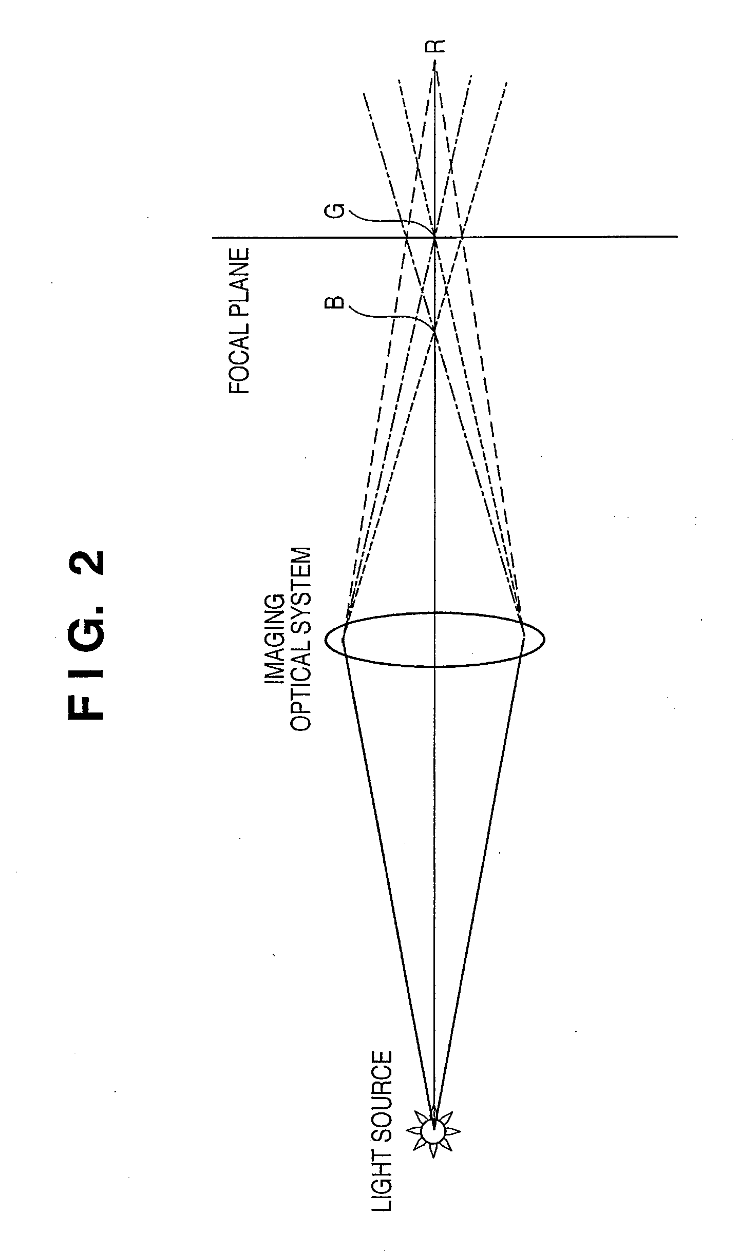
[0061]The color image capturing apparatus 100 comprises an imaging optical system 110, image sensor 120, A / D conversion unit 130, demosaicking unit 140, color fringing removing unit 150, vision correction unit 160, compression unit 170, and recording unit 180. Note that a field (object) f, and R (Red), G (Green), and B (Blue) rays shown in FIG. 2 are not building components of the color image capturing apparatus 100, but are shown in FIG. 3 for descriptive convenience.
[0062]In FIG. 3, the field f is imaged via the imaging optical system 110 on the image sensor 120 which photo-electrically converts an obje...
second embodiment
[0096]FIG. 11 shows an example of a color image capturing apparatus 200 to which an image processing method according to the second embodiment of the present invention is applicable. In FIG. 11, the same reference numerals as those in FIG. 3 denote the same functional parts.
[0097]The color image capturing apparatus 200 comprises an imaging optical system 210, a color separation prism 215, image sensors 220, an A / D conversion unit 230, a color conversion unit 235, a color fringing removing unit 250, a vision correction unit 160, a compression unit 170, and a recording unit 180.
[0098]The image sensors 220 according to the second embodiment are three CCD image sensors, unlike the first embodiment. The color separation prism 215 is added for the image sensors 220, and the demosaicking unit 140 in the first embodiment is omitted.
[0099]In FIG. 11, rays traveling from an object are formed into images on the image sensors 220 via the imaging optical system 210 and color separation prism 215...
third embodiment
[0122]FIG. 18 shows an example of a color image capturing apparatus 300 to which an image processing method according to the third embodiment of the present invention is applicable. In FIG. 18, the same reference numerals as those in FIG. 3 denote the same functional parts.
[0123]The color image capturing apparatus 300 comprises an imaging optical system 310, image sensor 120, A / D conversion unit 130, demosaicking unit 140, color fringing removing unit 350, vision correction unit 160, compression unit 170, and recording unit 180.
[0124]The imaging optical system 310 according to the third embodiment forms light traveling from an object into an image on the image sensor 120. Longitudinal chromatic aberration is sufficiently corrected by the imaging optical system 310 in the wavelength range of the G and B bands, but remains in the R band.
[0125]The following phenomenon occurs on the R, G, and B planes of a color image which is formed on the imaging optical system 310 and generated via t...
PUM
 Abstract
Description
Claims
Application Information
 - Generate Ideas
- Intellectual Property
- Life Sciences
- Materials
- Tech Scout
- Unparalleled Data Quality
- Higher Quality Content
- 60% Fewer Hallucinations
Browse by: Latest US Patents, China's latest patents, Technical Efficacy Thesaurus, Application Domain, Technology Topic, Popular Technical Reports.
© 2025 PatSnap. All rights reserved.Legal|Privacy policy|Modern Slavery Act Transparency Statement|Sitemap|About US| Contact US: help@patsnap.com


