
Excavation control system providing machine placement recommendation

a control system and excavating machine technology, applied in the direction of program control, navigation instruments, instruments, etc., can solve the problems of difficulty in positioning the excavating machine, material near the obstacle, damage to the machine and/or the obstacle,

Active Publication Date: 2008-06-05
CATERPILLAR INC
View PDF16 Cites 121 Cited by
  • Summary
  • Abstract
  • Description
  • Claims
  • Application Information

AI Technical Summary

Benefits of technology

[0006]One aspect of the present disclosure is direct to a control system for a machine operating at a excavation site. The control system may include a positioning device configured to determine a position of the machine, and a controller in communication with the positioning device. The controller may be configured to receive i

Problems solved by technology

These obstacles may include, among other things, underground utilities including power lines, gas pipelines, and pressurized water conduits; oil and / or fuel storage tanks; large boulders; and other similar obstacles.
When excavating in the vicinity of these obstacles, it may be difficult to position the excavation machine such that productive amounts of material may be removed before repositioning of the machine is required.
In addition, some of the material near the obstacle may, because of linkage constraints of the machine, only be removed from particular attack points.
If attempts are made to remove the material from positions other than these particular attack points, damage to the machine and / or obstacle may occur.
These problems may be exacerbated when an inexperienced operator is in control of the machine and / or when view of the obstacle is obstructed (e.g., when the obstacle is buried below the work surface).
Although the method and controller of the '370 publication may improve material removal near underground obstacles by visually displaying the obstacles relative to the earthworking machine and by preventing collisions between the obstacles and machine, they may be limited.
In particular, even with a visual display of the obstacles and collision prevention, it may still be difficult to properly position the machine and / or implement for efficient removal of the material.
Continually repositioning the machine and / or removing the material by hand can be inconvenient and inefficient.

Method used


Image

  • Excavation control system providing machine placement recommendation
  • Excavation control system providing machine placement recommendation
  • Excavation control system providing machine placement recommendation

Examples


Embodiment Construction

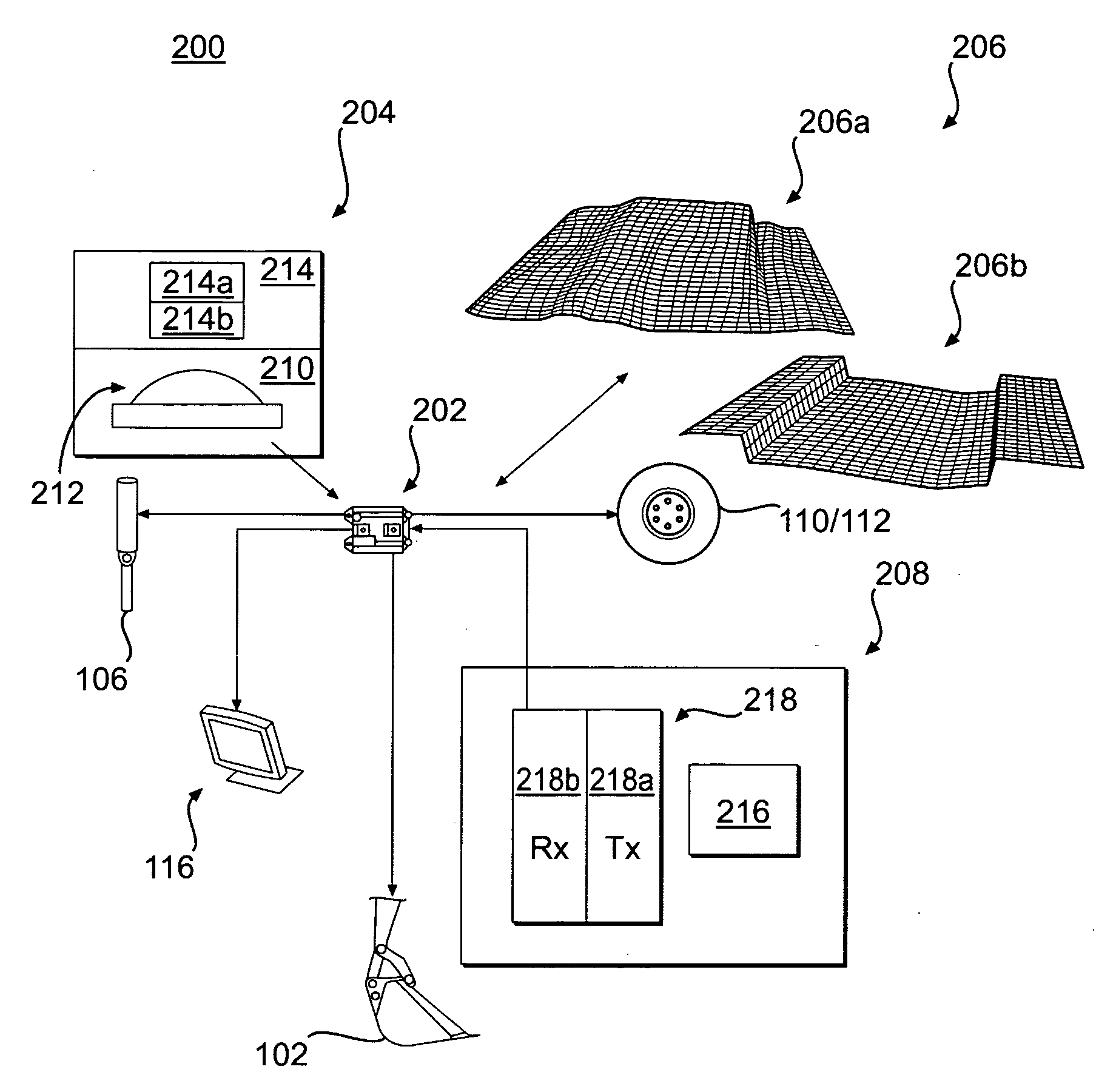
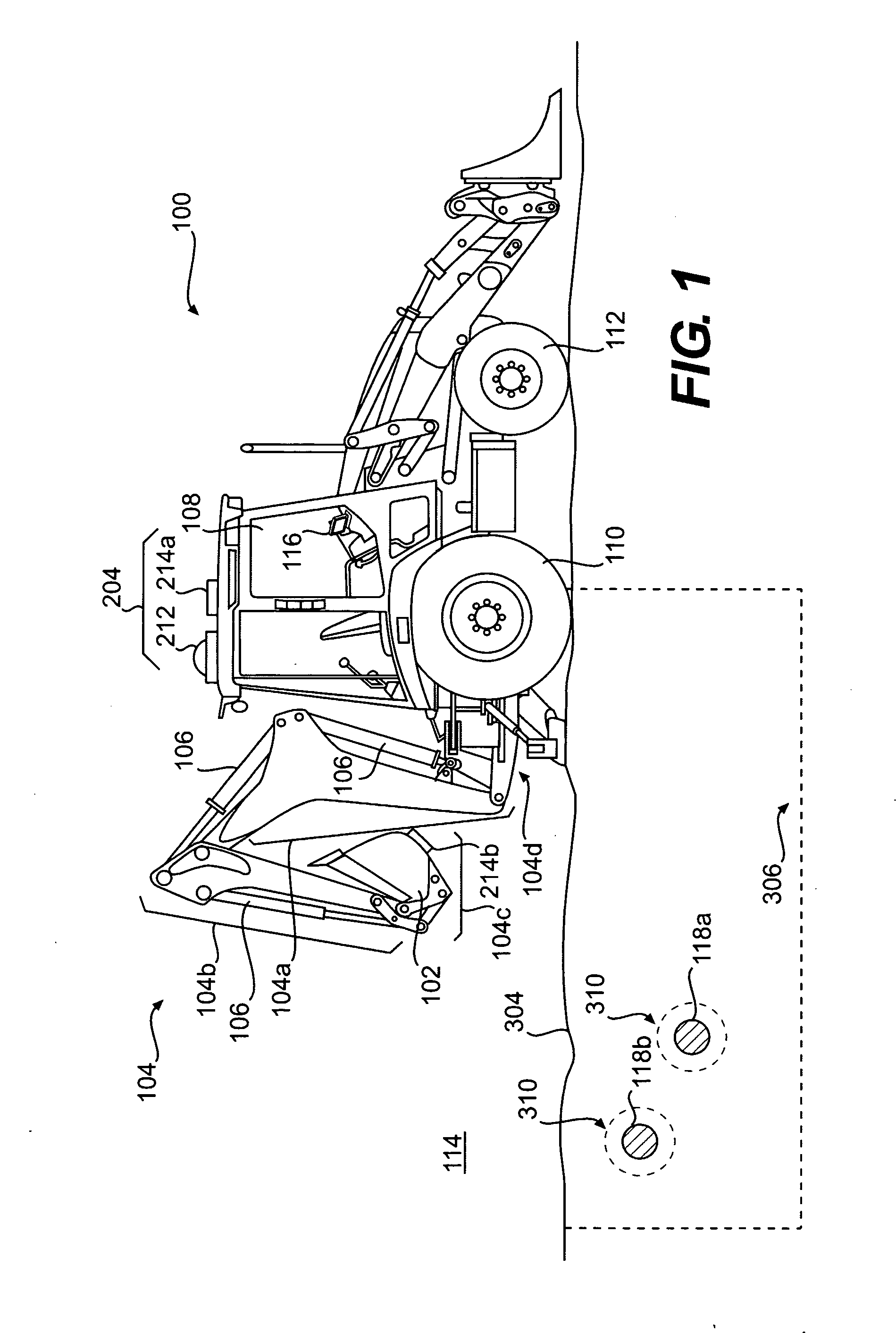
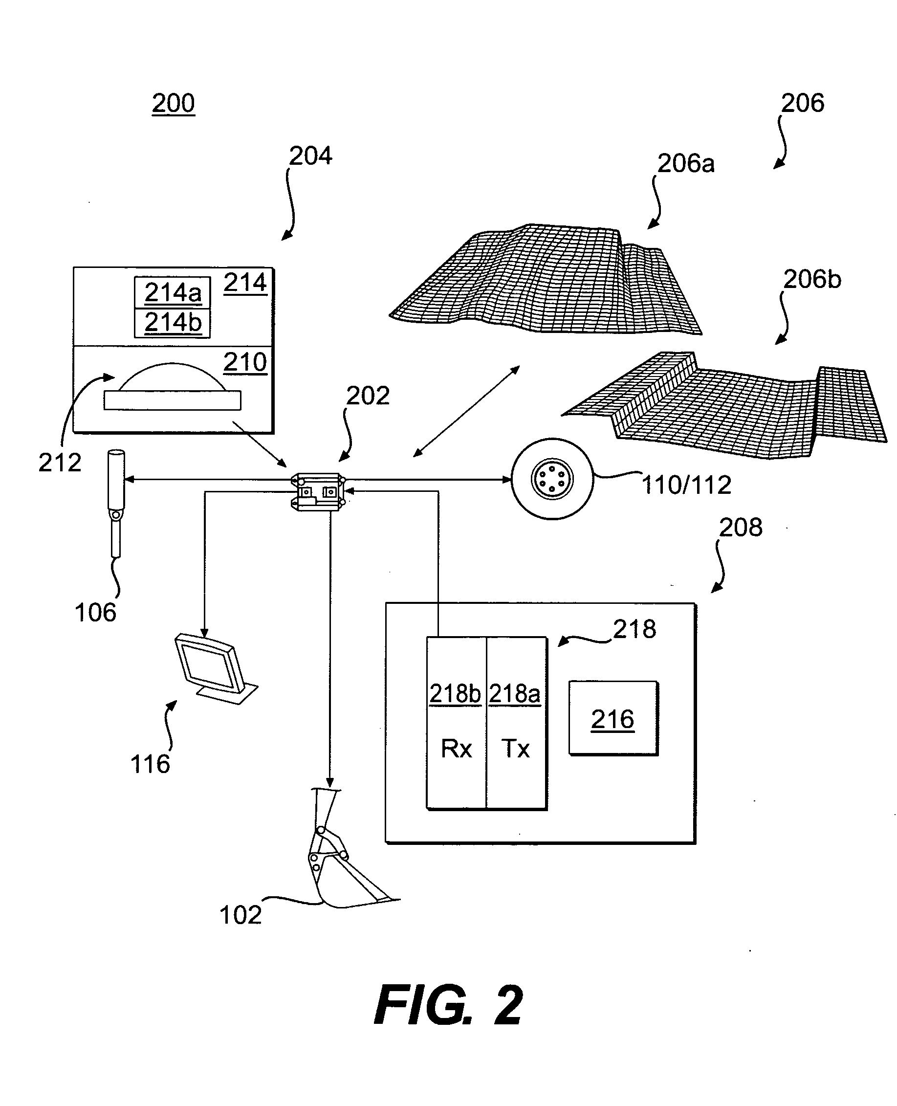
[0012]FIG. 1 illustrates an exemplary machine 100 for use in industries such as mining, construction, farming, transportation, or any other industry known in the art. Machine 100 may be, for example, a backhoe, a dozer, a loader, an excavator, a motor grader, a dump truck, or any other excavating machine known in the art. Machine 100 may include an earthmoving implement 102, such as a bucket, a shovel, a blade, a fork-arrangement, a grasping device, and the like. Implement 102 may be operably connected to machine 100 by way of a linkage system 104 comprising one or more interconnected arm members 104a-d.

[0013]One or more actuators 106 may be operably interconnected between arm members 104a-d to position and / or orient implement 102 with respect to machine 100 in a preferred manner. Actuators 106 may include, for example, one or more of a hydraulic or pneumatic cylinder, a pump, a motor, or any other type of actuator known in the art. Machine 100 may further include an operator cabin...


PUM


Abstract

A control system for a machine operating at a excavation site is disclosed. The control system may have a positioning device configured to determine a position of the machine, and a controller in communication with the positioning device. The controller may be configured to receive information regarding a predetermined task for the machine, receive the machine's position, and receive a location of an obstacle at the excavation site. The control system may also be configured to recommend placement of the machine to accomplish the predetermined task based on the received machine position and obstacle location.

Description

TECHNICAL FIELD[0001]The present disclosure is directed to an excavation control system and, more particularly, to an excavation control system that provides machine placement recommendations.BACKGROUND[0002]Excavation machines such as, for example, backhoes, tracked excavators, front shovels, trenchers, and other machines known in the art are often used to remove earthen material from around obstacles either to dig to the obstacles or to dig in spite of the obstacles so as not to disturb the obstacles. These obstacles may include, among other things, underground utilities including power lines, gas pipelines, and pressurized water conduits; oil and / or fuel storage tanks; large boulders; and other similar obstacles. When excavating in the vicinity of these obstacles, it may be difficult to position the excavation machine such that productive amounts of material may be removed before repositioning of the machine is required. In addition, some of the material near the obstacle may, be...

Claims


Application Information

Patent Timeline
IPC IPC(8): G06F7/00G01C21/00
CPCE02F3/435E02F9/245E02F9/2045
Inventor KOCH, ROGER D.
Owner CATERPILLAR INC
Learn More