
Dual pin turret lock for military vehicle

a dual-pin, military vehicle technology, applied in the direction of manufacturing tools, couplings, transportation and packaging, etc., can solve the problems of turret ring itself failing, prior art device working well, and now inadequa

Inactive Publication Date: 2008-06-05
ANCRA INTERNATIONAL CORPORATON
View PDF11 Cites 12 Cited by
  • Summary
  • Abstract
  • Description
  • Claims
  • Application Information

AI Technical Summary

Benefits of technology

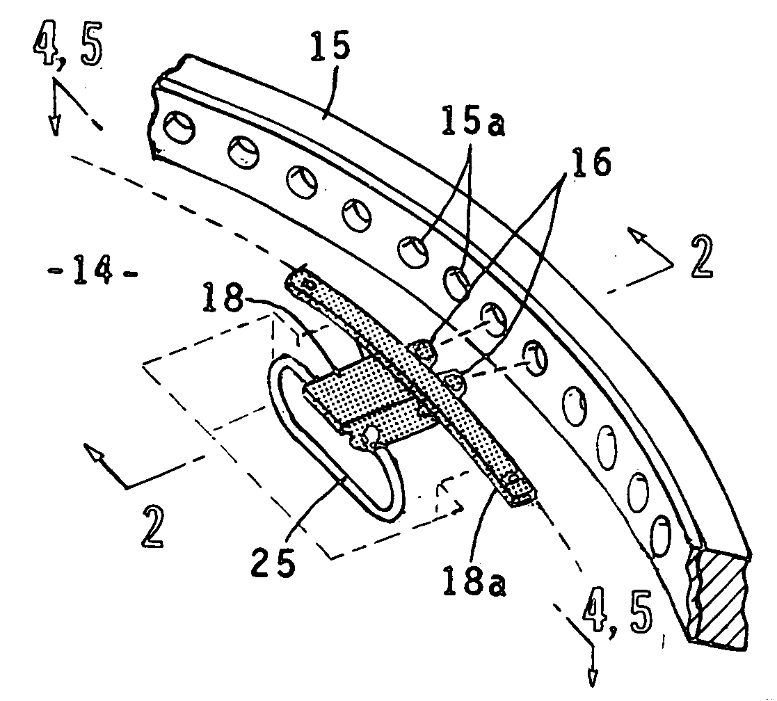
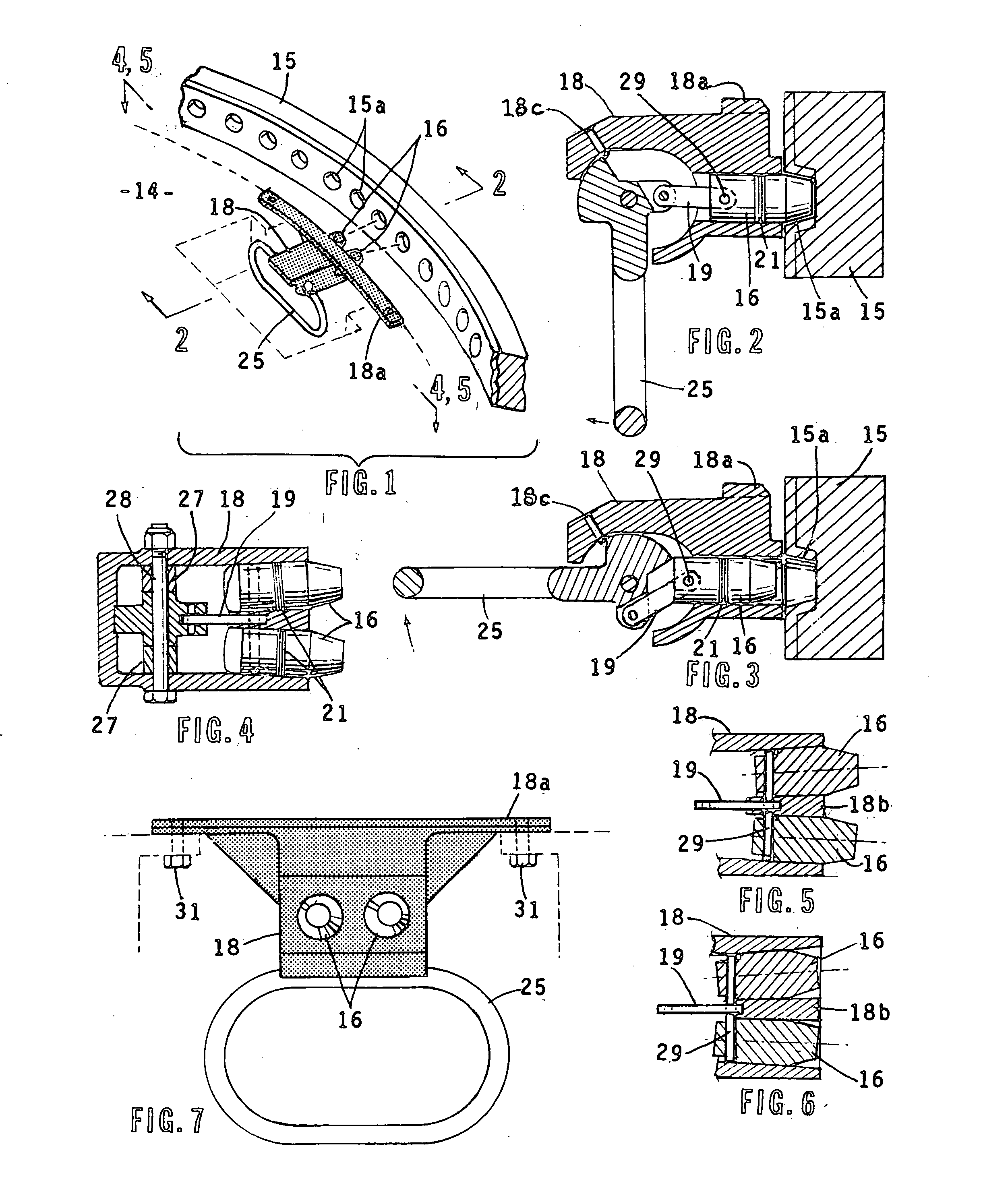
The present invention is a device that solves the problem of previous lock pins by using a pair of lock pins that share the load. These lock pins work together in response to a single control handle for installing and removing them. The lock pins are angled away from each other to allow them to enter adjacent holes in a radial configuration. The device is easy to use without any retraining of operating personnel. The invention employs a single handle to drive both lock pins into adjacent apertures in the fixed turret mounting ring. The lock pins are angled away from each other to accommodate the difference in entry angles of adjacent lock pins. The lock pin members have retaining rings to keep them in retention in the turret holes, but also allow for the withdrawal of the lock pin members for installation in another pair of apertures.

Problems solved by technology

This prior art device worked well for many years but is now inadequate due to the present use of much heavier weapons and turret armor.
The strengthening of the lock pin has been found not to solve the problem as the loads are now so great that the turret ring itself is failing under the loads involved.
Repairing the ring is quite difficult and expensive as it is part of the vehicle structure.

Method used


Image

  • Dual pin turret lock for military vehicle
  • Dual pin turret lock for military vehicle

Examples


Embodiment Construction

[0014]Referring to the drawings, a preferred embodiment of the invention is shown. The top portion of the vehicle, which may be a military tank or utility vehicle, has a rotatable turret 14 with a ring mounting portion 15 fixed to the body of the vehicle. Ring mounting portion 15 has a plurality of equally spaced holes 15a formed therein which run all the way around the ring portion.

[0015]The lock pin assembly includes a housing 18 in which lock pins 16 are contained. The housing has a top portion 18a which has a pair of holes on the opposite ends thereof through which screws 31 are fitted for attaching the housing 18 to the rotatable turret 14 of the vehicle. Handle 25 is pivotally supported on shaft 28. The handle is secured against unintentional movement by spring loaded ball detent 18c. Spacers 27 are installed along the sides of the handle to keep the handle in correct alignment. Link pin 19 is pivotally connected at one end to handle 25 and at the other end to rod 29, which is...


PUM


Abstract

The turret of a military vehicle such as a tank is locked in a predetermined position released from this position for installation in another position. The turret has a plurality of holes formed therein arranged in a circular configuration. A pair of lock pins are removably fitted within an adjacent pair of the holes. A single rod is pivotally connected to the lock pins with an operating handle pivotally attached to the rod. Retaining rings are installed on the ends of the rod to retain the lock pins on the rod. The lock pins are angled away from each other and slide on the rod to permit their free entry into adjacent holes. Movement of the handle in a first direction drives the lock pins into adjacent turret holes while movement in the opposite direction withdraws the lock pins from the holes for installation in another pair of holes to change the positioning of the turret.

Description

BACKGROUND OF THE INVENTION[0001]1. Field of the Invention[0002]This invention is related to a system and method for securing the turret of a military vehicle in a predesired position, which can readily be released for installation in another position[0003]2. Description of the Related Art[0004]Prior art turret locks for military vehicles utilize a single locking pin for retaining a turret in a desired position. The rotatable turret generally has a fixed mounting ring with equally spaced apart apertures in a radial configuration. To position the turret, a single lock pin is installed in any one of the apertures. The turret can be repositioned by relocating the lock pin to another aperture. This prior art device worked well for many years but is now inadequate due to the present use of much heavier weapons and turret armor. The strengthening of the lock pin has been found not to solve the problem as the loads are now so great that the turret ring itself is failing under the loads inv...

Claims


Application Information

Patent Timeline
Patent Type & Authority Applications(United States)
IPC IPC(8): B25G3/18
CPCF41H5/20F41H7/04Y10T403/595Y10T403/591Y10T403/598
Inventor BURROWS, WARD C.
Owner ANCRA INTERNATIONAL CORPORATON
Learn More