Self-adjusting load bar

Inactive Publication Date: 2008-06-05
INNOVENTOR ENG
View PDF14 Cites 5 Cited by
  • Summary
  • Abstract
  • Description
  • Claims
  • Application Information

AI Technical Summary

Benefits of technology

[0005]In one aspect, a method is provided for assembling a load bar assembly. The method includes providing a first linear stage having a first alignment mechanism that is configured to move the load bar assembly in a first direction. A second linear stage is provided that includes a second alignment mechanism that is configured to move the load bar in a second direction that is different from the first direction. The first alignment mechanism is positioned with respect to the second alignment mechanism such that the first alignment mechanism and the second alignment mechanism are prevented from being back-driven. The first alignment mechanism and the second alignment mechanism are configured to lock if one of the first alignment me

Problems solved by technology

In many aerospace and related industries, the loads being lifted by cranes are expensive, delicate, and require precise manipulation at many stages in the manufacturing process.
However, an automated system, especially one that is lifting heavy items, could easily injure personnel and damage equipment if a malfunction occurred.

Method used


Image

  • Self-adjusting load bar
  • Self-adjusting load bar
  • Self-adjusting load bar

Examples


Embodiment Construction

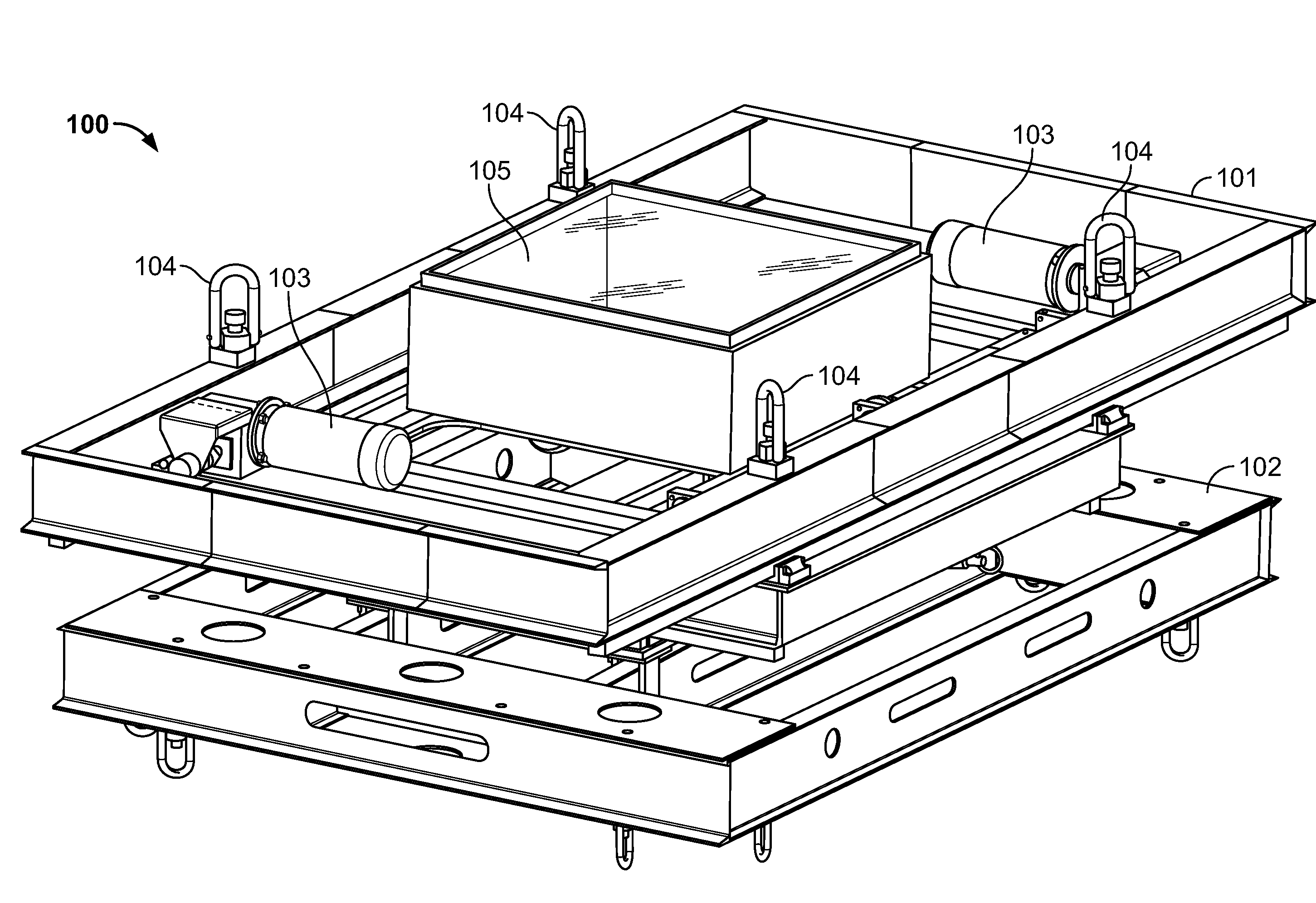
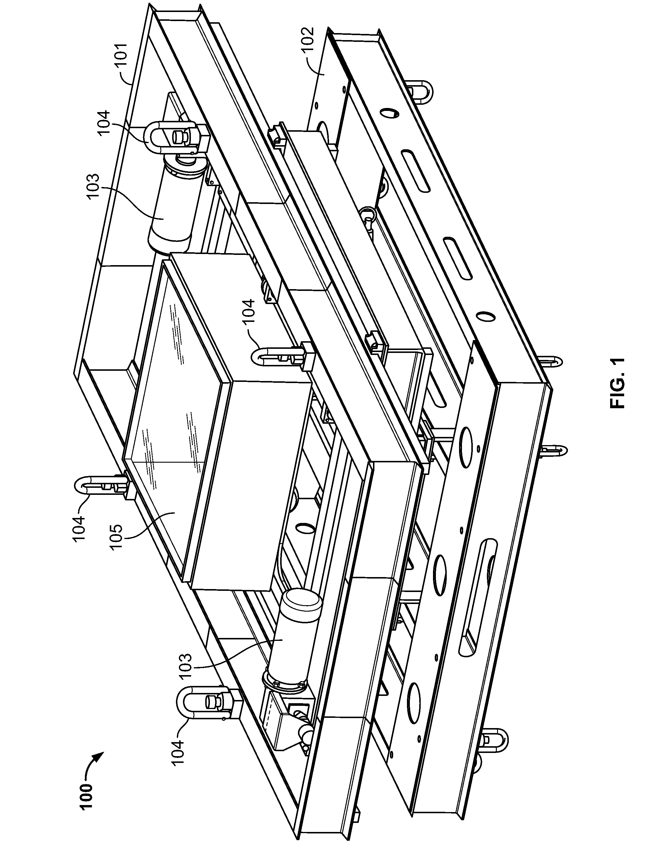
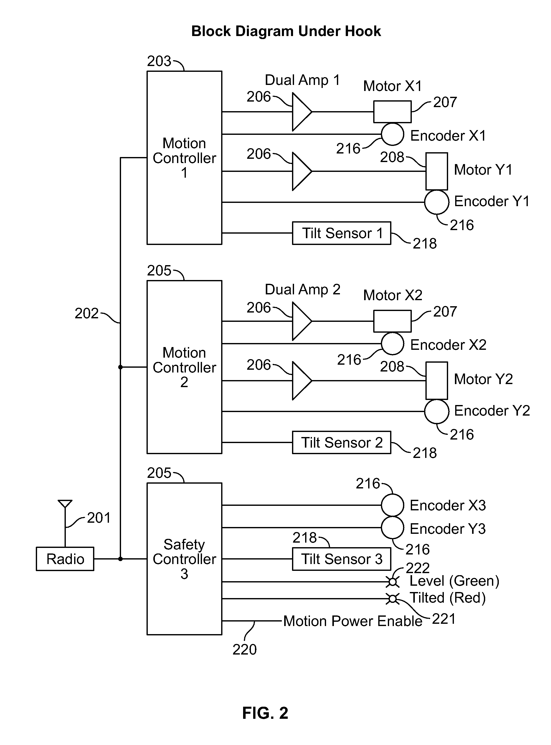
[0014]The load bar assembly described herein includes an X linear stage held by an overhead crane hook, and stacked on a Y direction linear stage that holds the load. Each linear stage contains dual-redundant motor drives with separate motors and controllers. Because the gear ratio of the linear screws is such that they cannot be back driven, the linear screws will lock mechanically if one of the drives fails. In addition, the screws will lock if the two drives are not synchronized. This prevents a motor / controller runaway from being able to move the device. Automatic leveling is achieved by the use of three redundant two-axis tilt sensors that provide input to motion control computers. Further, safety is enhanced by the inclusion of a deadman switch. Motor operation is not permitted unless this deadman switch is held closed by the operator.

[0015]FIG. 1 is a view of a self-adjusting load bar mechanism 100. An X frame 101 connects to the hook of the overhead crane using a four-way sl...


PUM


Abstract

A method is provided for assembling a load bar assembly. The method includes providing a first linear stage having a first alignment mechanism that is configured to move the load bar assembly in a first direction. A second linear stage is provided that includes a second alignment mechanism that is configured to move the load bar in a second direction that is different from the first direction. The first alignment mechanism is positioned with respect to the second alignment mechanism such that the first alignment mechanism and the second alignment mechanism are prevented from being back-driven. The first alignment mechanism and the second alignment mechanism are configured to lock if one of the first alignment mechanism and the second alignment mechanism fails.

Description

BACKGROUND OF THE INVENTION[0001]The invention relates to lifting fixtures used to precisely control the attitude of loads being handled by overhead cranes.[0002]In many aerospace and related industries, the loads being lifted by cranes are expensive, delicate, and require precise manipulation at many stages in the manufacturing process. This problem has been solved in the past by the design and construction of a large array of special fixtures or adapters each of which permit a single type load to be lifted. It is desirable from a cost and schedule standpoint to have a more universal solution. Specifically, it is desirable to have a single device that adapts itself to a larger number of load types.[0003]In lifting any load with an overhead crane, stability requires that the center of gravity of the load has to be directly below the hook. An automatic system must move the load in two dimensions relative to the hook so that a stable lift is possible. However, an automated system, esp...

Claims


Application Information

Patent Timeline
IPC IPC(8): B66C1/10B23Q3/00B25J9/10
CPCY10T29/49899B66C1/10
Inventor ALWAY, VERN J.TIMMER, MICHAEL L.
Owner INNOVENTOR ENG
Why Eureka
Try Eureka